Table of Contents
Advertisement
Quick Links
Met One Instruments, Inc.
1600 NW Washington Blvd.
Grants Pass, OR 97526
Tel: (541) 471-7111
Fax:(541) 471-7116
www.metone.com
C-12 Operation Manual - ©
publication may be reproduced, transmitted, transcribed, stored in a retrieval system, or translated into any other language in any
form without the express written permission of Met One Instruments, Inc.
B
C
LACK
ARBON
O
PERATION
C-12-9800 R
Copyright 2022 Met One Instruments, Inc. All Rights Reserved worldwide. No part of this
C-12-9800 Rev A
C-12
M
ONITOR
M
ANUAL
A
EV
Page 1
Advertisement
Table of Contents

Subscribe to Our Youtube Channel
Related Manuals for Met One Instruments C-12


Summary of Contents for Met One Instruments C-12
- Page 1 C-12 Operation Manual - © Copyright 2022 Met One Instruments, Inc. All Rights Reserved worldwide. No part of this publication may be reproduced, transmitted, transcribed, stored in a retrieval system, or translated into any other language in any form without the express written permission of Met One Instruments, Inc.
- Page 2 Page 2 C-12-9800 Rev A...
-
Page 3: Table Of Contents
Table of Contents INTRODUCTION About This Manual Technical Service C-12 – Black Carbon Monitor Safety Warnings C-12 Instrument Specifications SITE SELECTION AND POSITIONING CRITERIA SETUP & DEPLOYMENT Unpacking Electrical Service Shelter & Mounting Options Sample Inlet Configurations Assembling the C-12 LED and Toggle Switch User Interface 3.6.1... - Page 4 6.9.1 The CALIBRATE MENU Screen 6.9.2 The TEST MENU Screen 6.10 The ABOUT Screen MAINTENANCE AND TROUBLESHOOTING C-12 Error and Alarm Event Descriptions Basic Problem Causes/Solutions Table Suggested Periodic Maintenance Intervals Flow Audit and Calibration 7.4.1 Flow Sensor Calibration 7.4.2 Flow Audits The CALIBRATE AUDIT Menu –...
-
Page 5: Introduction
Please have the instrument serial number available when contacting the manufacturer. On most models manufactured by Met One Instruments, it will be located on a silver product label on the unit, and also printed on the calibration certificate. The serial number will begin with a letter and be followed by a unique four or five digit number such as U15915. -
Page 6: Black Carbon Monitor
The C-12 also has the option to add a 370 nm illumination channel. Data from the 370 nm and 880 nm channels may be used for source apportionment. Source apportionment allows one to determine if the measured BC originates from fossil fuel combustion or from biomass combustion. -
Page 7: Safety Warnings
It is equipped with an external desktop power supply module with a 100-240 VAC 50/60 Hz input range, and a 12 VDC, 3.34 A output. The C-12 instrument is housed in a weather-proof case for deployment outdoors. -
Page 8: Site Selection And Positioning Criteria
AC power outlet. It can simply be positioned in the area containing the air to be sampled based on local monitoring needs. 3 SETUP & DEPLOYMENT The C-12 is designed for easy setup and simple configuration for most applications. This section describes the basic assembly, setup, and start-up of the instrument. 3.1 Unpacking Unpack the carbon monitor and accessories and compare them to the packing list to make sure all items are present. -
Page 9: Electrical Service
3.2 Electrical Service The C-12 uses an internal DC power supply which can be supplied with 100 - 240 VAC, 50 or 60 Hz input power. The sampler is rated at 6 Watts maximum continuous power with the sample pump running. There are no hazardous live voltages located anywhere inside the instrument. The power supply provides a 12 VDC, 3.34 A output. -
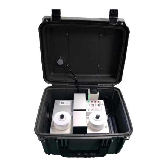
Page 10: Assembling The
3.5 Assembling the C-12 The C-12 is designed for easy setup and deployment. This allows it to be used for either permanent long-term sampling at a fixed site or for portable audit sampling for temporary applications. Figure 3-1 The C-12 Shown with Optional 83598 Stand The following describes the standard method of setting up the C-12. - Page 11 Tubing (4) LED Indicators USB B Serial Modem Connection Antenna Toggle switch Filter Tape Measurement Module Figure 3-2 C-12 Internal View TSP Inlet Solar Radiation Inlet Tube Shield Optional Lock Figure 3-3 C-12 External View C-12-9800 Rev A Page 11...
-
Page 12: Led And Toggle Switch User Interface
3.6 LED and Toggle Switch User Interface The C-12 has a simple user interface on the inside of the unit composed of four LED lights, a toggle switch (CTRL), and a USB type B serial port (COMM). The LED lights indicate if the sample is running or not, as well as if there are any errors within the device. -
Page 13: Toggle Control Switch Interface
The C-12 carbon monitor uses treated glass fiber filter tape rolls, available from Met One Instruments under part number 83599. It is essential that this tape be used in the C-12 in order to maintain proper instrument calibration and reproducibility. Since the filter tape advance frequency depends upon filter-loading, the frequency with which the tape needs to be replaced is variable. -
Page 14: Installing Filter Tape
Take-Up Reel (used filter tape) Rotates Clockwise Figure 3-5 C-12 Filter Tape Routing 3.7.2 Replacing Used Filter Tape 1. Use the toggle switch to open the measurement module, if not already open. See Step 2 above. 2. Loosen and remove the two tape reel knobs. -
Page 15: Starting And Stopping Sample Operation
3.8 Starting and Stopping Sample Operation When 12 VDC power is applied to the unit, the C-12 will boot up and get ready to immediately begin sampling. -
Page 16: Downloading And Viewing Data
4.1.1 How the Cloud Works The C-12 uses a cloud service for storing and viewing data. After the C-12 collects the data, it connects to the internet and designated secure Cloud site via its internal cell modem. Once connected it will push the data to the cloud site. -
Page 17: Data Retention
The C-12 unit itself holds 2,816 data records in case of a cloud modem failure. 4.2 Comet Software The C-12 is compatible with the free copy of the Comet™ program. Comet is a simple, Windows- based, communications terminal program developed by Met One Instruments, Inc. Comet allows the user to connect to the cloud and download the data from each cloud service webpage. -
Page 18: Comet Installation
Download the Comet software onto a PC and run the Windows Installer Package. Follow the on- screen instructions until Comet is successfully installed, then run it from the Programs directory. Create a new station for the C-12 and use it to retrieve the data from the monitor. 4.2.2 Setting up a Cloud Station The first time the Comet program is opened it prompts the user to create a new station for your Cloud site. - Page 19 Select the Met One Cloud Product Type and click next. Figure 4-4 Comet Product Type Screen Enter a Station ID, API key, and Serial Number for the C-12. Figure 4-5 Comet Cloud Information Screen Note: Customers will receive an API on the provided configuration sheet; a digital copy can be obtained from the Met One Instruments Service department.
-
Page 20: Data Plans And Renewals
When Comet downloads the data, a CSV file is created in the users My Documents folder. 5 DATA PLANS AND RENEWALS The C-12 includes one year of cellular data and website hosting at no extra charge. The cloud service can be renewed by contacting the Met One Service department at service@metone.com 541-471-7111. -
Page 21: Remote User Interface And Menu System
6 REMOTE USER INTERFACE and MENU SYSTEM The C-12 does not have a physical screen. A remote user interface is available by connecting the USB serial port of the unit to a PC or laptop with Met One Instruments, Inc. Comet software. -
Page 22: Main Sampling Screens
6.1 Main Sampling Screens The C-12 main sampling/operation screens are shown in Figure 6-2. The current date and time are always fixed at the top line of the display in these screens. The up/down arrow keys can be used to scroll to additional viewable parameters. -
Page 23: Menu Hierarchy And Navigation
Menu selections and instructions are detailed in the following sections of this operating manual as assigned in the Main Menu column of Table 6-2 above. Field editing in the C-12 is slightly different than the methods used in some of the other similar Met One Instruments, Inc. products. -
Page 24: Load Tape
Place the flashing cursor next to the STOP SAMPLE option at the top of the menu and press the ENTER key. The C-12 will ask the user to confirm if the sample should be stopped. If confirmed, the C-12 will stop running and return to the main menu. -
Page 25: View Alarm Log
Screen 6.6 The SETUP MENU The C-12 setup menu contains the settings and configuration parameters used by the instrument. The factory default values will be correct for most applications but can be reviewed and altered to suit the specific needs of the local monitoring program, as needed. The settings will not be lost if the unit is unplugged or powered down. -
Page 26: The Sample Setup Screen
Figure 6-11 The Sample Setup Menu 6.6.3 The MEMORY Setup Screen – Clearing the Memory The MEMORY screen is used to clear/erase files in the C-12 memory. CAUTION: This menu function will permanently delete the selected files from the instrument memory! Figure 6-12 The C-12 Clear Memory Menus The FILE value can be set to the DATA LOG, ALARM LOG, or ALL LOGS. -
Page 27: The Calibrate Menu
6.7.2 The CALIBRATE AUDIT Screens This series of screens is used to verify the optical measurement system of the C-12 monitor. A neutral density filter calibration tool is used in conjunction with these screens to perform the calibration audit. -
Page 28: The Test Menu
Figure 6-15 C-12 Sample Screen 6.8.1 The SELF TEST Screen The SELF TEST screen is used to activate an automatic test of most of the C-12 subsystems to verify that the instrument is in operational condition. Once the test is initiated, the instrument will test for properly loaded filter tape and test the function of all tape control hardware. -
Page 29: The Leak Test Screen
LED board is replaced. Select the 880 ON softkey to turn on the 880 nm LED. An option will be available to 370 nm if this option is employed in the C-12. Figure 6-23 – LED SET POINT Screen Contact service (Section 1.2) for more information. -
Page 30: Maintenance And Troubleshooting
7.1 C-12 Error and Alarm Event Descriptions The C-12 contains a system of error and alarm codes that are used to alert the operator to problems with the unit. The errors are stored in the digital alarm log with the time and type of the error. - Page 31 When the reference zero is above the Zero Limit. Signal Saturation Failure When the IR LED Signal reading is above the Saturation Limit. Reference Saturation Failure When the IR LED Reference reading is above the Saturation Limit. Table 7-2 Causes for Detector Alarms C-12-9800 Rev A Page 31...
-
Page 32: Basic Problem Causes/Solutions Table
Table 7-3 Set Points for Out of Range Alarms 7.2 Basic Problem Causes/Solutions Table The following table contains information on some of the more common C-12 problems that may be encountered, and some steps to identify and remedy the problems. Met One Instruments welcomes user suggestions for new items to include in this section of future manual revisions. -
Page 33: Suggested Periodic Maintenance Intervals
Table 7-4 Common Problems and Solutions 7.3 Suggested Periodic Maintenance Intervals Table 7-5 shows the Met One Instruments recommended periods for routine maintenance items. Some of these items will need to be performed more or less often depending on local conditions. -
Page 34: Flow Audit And Calibration
Flow calibrations require a traceable flow audit calibration device. The Met One Instruments, Inc. Swift 6.0 and similar particulate sampler flow calibrators work well. Attach the flow meter to the C- 12 sample inlet. The nominal flow rate for the C-12 is 1 lpm. Flow calibration devices should be selected accordingly. -
Page 35: Flow Audits
Once the zero test is complete, the span test must be performed using the 83011 neutral density (ND) filter. The measurement module will open, and the screen will display instructions to insert the ND Filter as shown in Figure 7-5. C-12-9800 Rev A Page 35... - Page 36 Figure 7-6) for the span filter portion of the test. At the end of the test, the measurement module will open and the results will be displayed as shown in Figure 7-7. Note: Figure 7-7 and Figure 7-8 display results with the optional C-12 BRC 370 UV option. Standard configuration CALIBRATE AUDIT results will only display BC results.
-
Page 37: Flow System Leak Checks
Be sure to replace the tape prior to beginning the leak check. The C-12 flow contains an easy to maintain flow system. To perform a leak test, remove the TSP cap from the sample inlet and place the vinyl cap (pn: 770025) over the inlet tube. Navigate to the TEST MENU >... -
Page 38: Data Retrieval And Communications
8.1 C-12 Data Outputs and Data Examples The SETTINGS File: The settings file contains most of the setup menu parameters for the C-12. This file should be reviewed periodically to ensure that no settings have been incorrectly changed. It also serves as a good data validation record. -
Page 39: Flash Firmware Upgrades
The User Data File: The top of the C-12 User Data file contains the header information for the file, including the name of the report, the time stamp at which the report was requested, the location id and the serial number of the device. - Page 40 2. A PC or laptop with a USB port must be available and the USB drivers for the C-12 installed. Install the Firmware Update Utility program onto the computer by following the prompts after following the e-mail link to the Met One FTP site.
-
Page 41: Accessories And Parts
9 ACCESSORIES and PARTS The following parts are available from Met One Instruments for maintenance, replacement, service, and upgrades. If unsure about a part, please contact the technical service department. Some of these parts may require technical skills or special instructions before use or installation.
Need help?
Do you have a question about the C-12 and is the answer not in the manual?
Questions and answers