Table of Contents
Advertisement
Quick Links
Advertisement
Table of Contents

Subscribe to Our Youtube Channel
Related Manuals for PRÜFTECHNIK FLUKE VIB 6.12 Series


Summary of Contents for PRÜFTECHNIK FLUKE VIB 6.12 Series
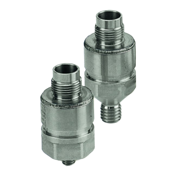
- Page 1 Accelerometer (Industrial) VIB 6.12x, VIB 6.14x Installation and Operation...
- Page 2 Sensors of series VIB 6.12x / VIB 6.14x are used • The permissible ambient temperature range is in industry to measure the following parameters: between -30°C and +80°C [-22°F ... + 176°F]. – Vibration acceleration on rotating machines • The European installation regulations are to be –...
- Page 3 Technical data VIB 6.122 R / DEX VIB 6.127 / DEX PARAMETER VIB 6.125 R / RIP / IDEX VIB 6.129 IP / IDEX VIB 6.142 R / DEX VIB 6.147 / DEX Signaling system Current Line Drive (CLD) Transmission factor 1.0 µA/ms [9.8 µA/g] ±...
- Page 4 Installation Drill threaded hole M8 / 90 ° • Drill pilot hole: 3.5 mm / 15 mm deep (B). The frequency behavior and dynamic range of the • Bore out hole: 6.8 mm / 15 mm deep (C). sensor can be heavily influenced by installation. •...
- Page 5 Adhesive mounting apply additional adhesive around the bonding location for greater stability. Applies to sensors of series VIB 6.12x, VIB 6.14x, • If necessary, use adhesive tape to hold the and appropriate mounting adapters VIB 3.431 / adapter in place during hardening. VIB 3.430.
- Page 6 Electrical connection Extend the cable The signal is transmitted via a coaxial cable. On • Observe the maximum cable lengths (see the the sensor side, the cable is assembled with a device installation manual). TNC plug and, if necessary, equipped with pro- •...
- Page 7 Ex-zone – In this regard, the relevant implementation pro- visions are to be observed. This also applies to If the cable ends are connected inside the Ex- provisions relating to the safety of the connec- zone, the ignition protection type must not be tion type.
- Page 8 Connection examples for the Ex-zone CMS, without EX-protection 250V VIBXPERT EX VIBSCANNER EX Machine Not connected Coaxial Triaxial 50 mm Triaxial EX i VIB 3.550 A: VIB 93036 S / VIB 93036 F / VIB 91000 B: VIB 6.12x DEX Coaxial C: Protective terminal housing, plastic D: Protective terminal housing, metallic, mounted and insulated, housing at PA...
Need help?
Do you have a question about the FLUKE VIB 6.12 Series and is the answer not in the manual?
Questions and answers