Table of Contents
Advertisement
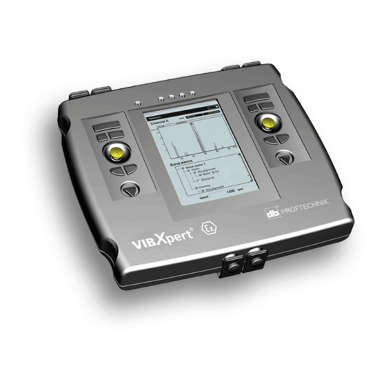
VIBXPERT
VIBXPERT
2-channel
FFT data collector
and signal analyzer
Operating
Instructions
Series: VIB 5.300 / VIB 5.300 EX
Firmware version: 2.3x
0044
Edition:
November 2010
Order no.: VIB 9.805.G
Original manual
®
®
EX
Dear customer,
We are grateful for your trust and hope that you are happy
with our product. If you have any suggestions for improving
this product or this instruction manual, please let us know.
PRÜFTECHNIK Condition Monitoring
Fax: +49 89 99616-300
eMail: info@pruftechnik.com
1-1
Advertisement
Table of Contents

Related Manuals for PRÜFTECHNIK VIBXPERT


Summary of Contents for PRÜFTECHNIK VIBXPERT
- Page 1 VIBXPERT ® ® VIBXPERT 2-channel FFT data collector and signal analyzer Operating Instructions Dear customer, Series: VIB 5.300 / VIB 5.300 EX Firmware version: 2.3x We are grateful for your trust and hope that you are happy with our product. If you have any suggestions for improving this product or this instruction manual, please let us know.
- Page 2 OMNITREND maintenance software for evalua- tion, archiving and documentation. The combination of its extensive range of features and easy operation makes VIBXPERT the effective choice for a wide range of applications: • High measurement accuracy and high-speed data collection • Operating modes:...
- Page 3 • Online, context-sensitive HELP Power supply • Lithium-Ion battery of latest generation for more than 8 hours of operation • Smart battery charging in VIBXPERT or in external charging station. • Automatic power management (display illumination, device) Communication • Fully networkable •...
- Page 4 'Multimode', Templates' and 'Route' operating modes. The operation of the optional ‘Balancing’ module is described in the ‘VIBXPERT - Balancing’ operating manual (VIB 9.806.G). If you don't have this manual handy, open the online help in the device with the HELP key.
-
Page 5: Table Of Contents
VIBXPERT delivery packages ............1-9 Safety and operating notes ............1-12 Chapter 2: Getting started ..........2-1 VIBXPERT FFT data collector and signal analyzer ......2-1 Keyboard ....................2-2 Status display per LED ................. 2-3 Notes on operation ..............2-4 Interfaces ................... - Page 6 Contents Chapter 3: Measurement........... 3-1 Preparation ................3-1 What is a measurement task? ..............3-2 Multimode: Measurement, Analysis, Diagnosis ......3-3 Typical workflow of a measurement ............3-3 Starting a measurement: ................3-3 Continuous measurement (live mode) ............3-4 Save result ....................3-4 Measurement of a route ............
- Page 7 Printing out the PDF file ................6-4 VIBXPERT utility ................. 6-5 Installing and starting the program .............. 6-5 Registering optional functions ..............6-6 Setting up a connection with VIBXPERT ............6-7 Configuring VIBXPERT ................. 6-7 Transferring files ..................6-8 Transferring system files ................6-9 VIBCODE .................
-
Page 8: Chapter 1: Introduction
Delivery packages Chapter 1: Introduction The scope of supply for VIBXPERT without EX protection includes the basic packages with and without OMNITREND software and contains the following components. If you discover that a part is missing or is damaged, please contact your PRÜFTECHNIK agent immediately. -
Page 9: Vibxpert Delivery Packages
VIBXPERT delivery packages VIBXPERT delivery packages Basic package, 1-channel device VIB 5.360-1E VIB 5.300 VIB 5.354 VIB 5.329 (VIB 5.325) VIB 5.320 VIB 6.142R VIB 3.420 VIB 5.330SUSB VIB 9.805.G VIB 9.806.G VIB 5.436 VIB 9.807.G VIB 9.661-5DG Basic package 'Trending', 1-channel device VIB 5.364-1E... - Page 10 Technical data sheet, UNV communication adapter VIB 5.364-1EX 'Trending' package for 1-channel device includes all parts of 'Diagnosis' package plus VIB 8.981 OMNITREND for VIBXPERT, PC software (instead of VIB 8.970) VIB 9.631.G Getting started with OMNITREND Not shown: VIB 8.981-P PC licence for VIBXPERT VIB 8.981-OMT...
- Page 11 1-11 VIBXPERT delivery packages 'Diagnosis', 1-channel device, intrinsically safe VIB 5.360-1EX 'Trending' VIB 5.364-1EX Includes all 'Diagnosis' package components plus the following: VIB 8.981 VIB 5.329 X VIB 5.300 EX VIB 5.354-LD VIB 9.631.G VIB 6.142 DEX VIB 5.322 (VIB 5.323) VIB 5.330-UNV...
-
Page 12: Safety And Operating Notes
This symbol denotes information and tips on operating the data collector. Note Information related to VIBXPERT with intrinsic safety. Intended use - The measurement device may only be used for the measurement of machine signals in industrial environments while taking into consideration the technical specifications (see "... - Page 13 (VIB 5.434) and extra-low signal voltages (VIB 5.433). Under no circumstances should you recharge the battery. Under no circumstances should you use the VIBXPERT case (VIB 5.329). The device may only be connected outside the hazardous area ** The computer meets the require- to a computer**.
- Page 14 = 0,8mH LAN/USB circuit Do not use this interface in an explosive environment! Only devices with V < 6V or the communication adapter for VIBXPERT EX (order no. VIB 5.330 UNV) may be connected for data transmission purposes. Battery load circuit Do not use this interface in an explosive environment! To charge the batteries, use chargers VIB 5.322 and VIB 5.323 only!
- Page 15 1-15 Safety and operating notes The diagram below shows the location and the contents of the device nameplate (intrinsic safe version). Nameplate for the VIBXPERT EX device with serial number ('S.No.') and safety notes. 50°C 50100...
- Page 16 Nameplates The diagram below shows the locations and the contents of the device nameplate and the battery nameplate (standard version). 00100 Nameplate for the VIBXPERT device with serial number ('S.No.') Nameplate for the rechargeable battery with with serial number and...
-
Page 17: Chapter 2: Getting Started
Getting started Chapter 2: Getting started VIBXPERT FFT data collector and signal analyzer The illustrations show the interfaces and operating elements of the measurement device without explosion protection (below) and with explosion protection (right): Light sensor: - Keyboard illumination LEDs:... -
Page 18: Keyboard
The keys and the joystick are ergonomically arranged so that VIBXPERT can be comfortably operated with the thumb of the right hand. In VIBXPERT with intrinsic safety, the keyboard is on the left and right sides. The keyboard automatically illuminates in dark surroundings. -
Page 19: Status Display Per Led
Flashing LEDs have the higher priority, i.e RED flashes with signal overload and alarm level exceeded. Ambient YELLOW BLUE light sensor GREEN Arrangement of the LEDs on VIBXPERT (left) and on VIBXPERT EX (right) YELLOW GREEN BLUE Ambient light sensor Status and alarm indication... -
Page 20: Notes On Operation
To switch on the device, hold the On/Off key down for two seconds. Switching on VIBXPERT VIBXPERT is ready for operation when the start screen appears. To switch off, press the On/Off key again for 2 seconds and confirm the resulting query to switch off with 'YES'. -
Page 21: Interfaces
Getting started - Interfaces Interfaces The connections for the sensor and data cables are located on the front of the measurement device. The cable connectors and sockets are colored for easy identification. To unplug the connector, push the connector sleeve backwards to release the lock. -
Page 22: Interfaces On Vibxpert With Intrinsic Safety
The interface functions are basically the same as in the non-EX device. They differ in the following ways: - VIBXPERT with intrinsic safety has a separate charging socket on the bottom of the device. Thus, the channels marked in blue are used for measuring analog signals only. -
Page 23: Power Supply
Getting started - Power supply Power supply VIBXPERT is supplied with energy by a Lithium-Ion rechargeable battery (VIB 5.325, Power supply - intr. safe device, P. 2-9). The residual charge of the battery is displayed above the battery icon on... -
Page 24: Charging In The External Charging Station
Getting started - Power supply During extended periods of non-use and during storage, connect VIBXPERT regularly to the mains supply. This prevents the battery from becoming completely discharged, and the date and time settings are retained. • Do not use damaged batteries! •... -
Page 25: Power Supply - Intrinsically Safe Device
Getting started - Power supply Power supply - intrinsically safe device The battery in VIBXPERT with intrinsic safety is permanently in- stalled in the housing and may only be replaced by authorized PRÜFTECHNIK employees. To charge the battery, connect the charger (VIB 5.322 or VIB 5.323) to the charging socket and the power outlet. -
Page 26: Memory Card
Memory card A CompactFlash (CF) card with 2 GB memory capacity is installed in the VIBXPERT as standard (EX ver.: 1 GB). If required, the standard card can be replaced by a card with greater memory capacity*. Memory cards that are tested and approved by PRÜFTECHNIK for use with VIBXPERT, see the document 'Technical Info # CM14', available on request or on the Internet: www.pruftechnik.com... - Page 27 When the device is switched on, the card is automatically tested. The following scenarios are possible: Card formatted, which version? - The card is new and has not yet been formatted in a VIBXPERT: you are prompted to format the card. - The card has already been used in another VIBXPERT: Card version <...
-
Page 28: Basic Settings - Device Setup
2-12 Getting started - Basic settings Basic settings - Device Setup Before carrying out measurements with VIBXPERT, the basic settings in the 'Device Setup' should be checked and changed if necessary. • Switch on VIBXPERT. • Click on 'Device Setup' in the start screen. The 'Device Setup' screen appears. -
Page 29: Display Settings, Switchoff And Additional Options
To protect the display against damage, it is covered with a scratchproof transparent film. The film is easy to remove. Attention! In the VIBXPERT with explosion protection, you must remove this film before using the measurement device in explosive areas. Display settings... -
Page 30: Route
2-14 Getting started - Basic settings Route • Click on 'Route' in the 'Device Setup'. Device Setup The settings in the Route Setup apply to measurements in the 'Route' / 'Template' mode. The Route Setup can be called up and adjusted at any time in the route/template. - Page 31 2-15 Getting started - Basic settings : Display of machine images. The position of the measure- NABLED ment locations and the measurement direction is indicated by symbols. : The route is processed in the set display mode (tree / list) ISABLED Display all hierarchies This option applies to the tree view only.
- Page 32 OMNITREND. Optimize meas. time for MultiTask The individual measurements are performed with a sensor but are processed in parallel on 2 channels in VIBXPERT. : Measurements are internally distributed to both measure- NABLED ment channels and are processed in parallel.
- Page 33 : Sensor detection is active. Prior to every measurement, ISABLED VIBXPERT checks whether the correct sensor is connected and if the cable is OK. A sensor icon appears at the upper edge of the screen next to the battery icon.
- Page 34 2-18 Getting started - Basic settings Save settings • Click on 'Saving' to set up the following options: Device Setup AutoSave This shortens the duration of the entire measurement. : The selected time (0 ... 10s) corresponds to the waiting NABLED time until the result is automatically saved.
-
Page 35: Transducers
Available transducer Preselecting available transducers As it is probable that not all the transducers stored in VIBXPERT will be used, the choice can be restricted to those transducers that are available to the user. When setting up the measurement tasks,... - Page 36 2-20 Getting started - Basic settings Transducer parameters To check the parameters for transducers that have already been set up, proceed as follows: • Select the transducer. • Press the MENU key. • Click on 'Show'* or 'Edit' to open the parameter screen (see *'Show' appears for factory-defined transducers whose parameters cannot below).
- Page 37 2-21 Getting started - Basic settings ESONANCE FREQUENCY The resonant frequency of the sensor is an important influencing quantity in the shock pulse measurement (bearing condition). (RPM) ETTLING TIME Settling time of the RPM sensor Filtering the transducer list The transducer list can be can filtered according to specific criteria: •...
-
Page 38: Tranducer Detection And Hardware Settling
Tranducer detection and Hardware settling In this menu, the transducer detection feature and the settling of the amplifier stages in VIBXPERT can be switched on and off. Additional Device Setup information can be found in the 'Route Setup' section (p. 2-17). -
Page 39: Keyphaser
The functions and operating modes in VIBXPERT are distributed in individual modules* that can be enabled by password as required. VIBXPERT is supplied in the 'Basic' version with which overall values *The attachment on page 6-22 as well as (limited) spectra can be measured. For example, to enable... -
Page 40: Units
This is generally performed by entering the PC license password in OMNITREND. Here you can enter the password in VIBXPERT, which is then automatically read into the software to register the device when it first makes contact with OMNITREND. -
Page 41: Key Controls
Additional key on the rear panel * non-EX device VIBXPERT has an additional input key on the rear panel which can be operated with the index finger of the left hand (see below). This key can be used as an additional ENTER key or for starting a measure- ment. -
Page 42: Printer
The test page is printed as soon as the print job has been processed by VIBXPERT. If you select 'PDF' as the printer, you can print the PDF file directly from the measurement device (see page 6-4) or transfer the PDF file to a PC using the 'VIBXPERT utility' tool (see p. -
Page 43: Deleting A Print Job
2-27 Getting started - Basic settings Deleting a print job • Click on 'Print queue' in the 'Printer settings' menu. • Select the print job in the list. Device Setup • Press the MENU key and click on 'Delete job'. If a print job is being processed, a print icon appears at the top edge of the screen. -
Page 44: Analog Out/Headphones
2-28 Getting started - Basic settings Analog out/headphones At the analog output (yellow connector), the vibration signal can be picked up with a suitable analysis device (oscilloscope) or listened to via headphones (e.g. VIB 6.670). The output is always the pure, non- integrated signal without the DC component. -
Page 45: Service Menu
2-29 Getting started - Basic settings Service menu • Click on the 'Service' icon to open the Service main menu (see below). Device Setup A series of functions are available for service, maintenance and training purposes. For clarity, the numerous settings are grouped into submenus (see below): Device Info This menu contains device information for service and repair as well... -
Page 46: Loglevel
Demo For training or demonstration purposes, the VIBXPERT screen display can be shown on a PC monitor with the aid of the VIBXPERT demo program. VIBXPERT must be switched to 'Demo' mode for this. • Click on the 'Demo' icon. The following options can be selected:... -
Page 47: Memory Card (Cf)
2-31 Getting started - Basic settings To backup the log file on the memory card in the VIBXPERT, click on the 'Backup Log' icon and confirm the prompt with 'Yes'. The log file can be transferred to the PC using the 'VIBXPERT update tool'. -
Page 48: Data Transfer
Measurement tasks, measurement data and machine templates are transferred using the OMNITREND PC software. All other data are exchanged via the 'VIBXPERT utility' tool found on the PRÜFTECH- NIK CD and that must be installed locally on the PC. Direct connection to laptop/PC VIBXPERT without intrinsic safety : Connect the PC cable VIB 5.430-2 to the digital... -
Page 49: Network Connection
Data transfer via an Ethernet network requires the following compo- nents and information: - Network connection - Ethernet cable for VIBXPERT (VIB 5.331), or universal communi- cation adapter for VIBXPERT EX (VIB 5.330 UNV) - PC with network interface card connected to the network/hub... -
Page 50: Setting Up The Network Communication
VIB 5.331 Ethernet VIB 5.330 UNV Ethernet Setting up the network communication • Connect VIBXPERT to the network (see above). • Switch on VIBXPERT. • Click on 'Device Setup' in the start screen, and then on 'Ethernet': Device Setup Left:... -
Page 51: Ip Address Of The Local Pc In The Network
Take the first three numbers of your PC's IP address and change the last number only (see also the following instructions). Make sure that the IP address for VIBXPERT is not already allocated in the network. Contact your system administrator if you work in a company network. -
Page 52: Entering A Fix Ip Address For The Local Pc
2-36 Getting started - Data transfer Entering a fix IP address for the local PC You must assign a fixed IP address to the computer if you connect the computer directly to the measurement device with a patch cable (see p. -
Page 53: Update
PRÜFTECHNIK Condition Monitoring CD. • Connect VIBXPERT to the network / the PC. • Switch on VIBXPERT. • Start the 'VIBXPERT update tool'* on the PC and click on <Next> * Alternatively, the VIBXPERT Update to call up 'Step 2': tool can also be stared using the 'VIBXPERT utility' tool (see p. - Page 54 • The device switches itself on and off repeatedly until the update is completed. This process generally takes a few minutes. Wait for the VIBXPERT start screen to appear. The version number appears in the lower right corner of the start screen: 2.20...
-
Page 55: Chapter 3: Measurement
OMNITREND PC software for evaluation and archiving purposes. Balancing: * 'Balancing' mode is described in the VIBXPERT can be used for dynamic balancing* in one or two planes. VIBXPERT 'Balancing' manual (VIB 9.806.G). Preparation Before beginning a measurement, ensure that ... -
Page 56: What Is A Measurement Task
To simplify the preparation of a 'multimode' measurement and to RPM, save the user from having to enter the required data, VIBXPERT already contains a comprehensive collection of predefined knowl- edge-based measurement tasks. The user is only allowed to change the transducer and to alter the measurement channel in these measurement tasks. -
Page 57: Multimode: Measurement, Analysis, Diagnosis
Measurement - Multimode Multimode: Measurement, Analysis, Diagnosis To activate the 'Multimode' mode, click on the corresponding symbol in the start screen. The measurement tasks appear in the selection screen (see below). The measurement task for the marked icon is displayed below the icon field. The measurement tasks are grouped into three tabs: Overall (charac- teristic) Values, Signals, Advanced (measurements). -
Page 58: Continuous Measurement (Live Mode)
Measurement - Multimode Before every measurement, VIBXPERT checks that the sensor and cables are correctly connected if sensor detection is activated in the Note device setup (p. 2-22). In measurements with trigger (phase, orbit,...) the trigger signal is monitored (green LED flashes at every pulse). -
Page 59: Measurement Of A Route
Measurement of a route The 'Route' mode processes a specified number of measurement tasks which are carried out regularly according to a specific schedule with VIBXPERT. The measurement tasks for a route are compiled on the PC using the OMNITREND software. Preliminary remarks A route can be carried out in the specified sequence or in any order;... - Page 60 / heavily contaminated’). The machine condition is inspected in situ and the applicable option selected from a list. Manual entry This measurement task allows numerical measurement values that were acquired from another measurement device or read on a display instrument (e.g. flow rate, pressure,...) to be entered in VIBXPERT.
-
Page 61: Notes About Routes
Measurement - Route Notes about routes A route can contain the following information: - Alarm and warning thresholds - Reference results that define the good machine condition. - Historic measurement results - Frequency marks - Master data of the route (name, user, version, ...) To display the master data, highlight the route in the route list (see below), press the MENU button and click on ‘Info’. - Page 62 Measurement - Route Notes about the tree view: - If the tree is not fully opened, click on a node (‘Machine train’ or ‘Machine’) (see figure to the left and p. 2-4). Note - If the 'Graphic Route' option is activated (p. 2-14), you can select the measurement location using the machine graphic (see left).
-
Page 63: Icons
Measurement - Route Icons Meas. task Measurement task completed Measurement task skipped Adaptive task Diagnostic task, triggered by ‘adaptive trigger’ Reference RPM AWP Result exceeds alarm, warning, prewarning threshold Status in Tree view / List view (empty): Partly/ not processed : Completely processed : Skipped : Partly processed and skipped... -
Page 64: Menu Functions In The Tree / List View
3-10 Measurement - Route MENU functions in the tree / list view • Press the MENU key in the tree / list view (see below): NSKIP If a machine is not in operation during a route, you can skip all measurement tasks planned at this machine. - Page 65 3-11 Measurement - Route The following information is displayed for the highlighted element - Path in the OMNITREND database - Hierarchy type (e.g. train) - ID (identification number in the database) - Sequence number = order of the elements in the route list view - Task statistics (measured, skipped, not measured) - VIBCODE code number and code ring pattern (‘Show VIBCODE’).
-
Page 66: Menu Functions In The Measurement Task Selection Screen
3-12 Measurement - Route MENU functions in the measurement task selection screen • Press the MENU key in the task selection screen (see below): NSKIP A measurement task can be skipped if it cannot be measured. VENT OMMENT Enter the event and, if necessary, a supplementary comment to explain the result. -
Page 67: Measuring With A Machine Template
3-13 Measurement - Machine template Measuring with a machine template A 'Machine template' is used if it is necessary to carry out measure- ments on machines of the same type. The measurement locations are always at the same position and the measurement tasks are identical for each machine. -
Page 68: Preliminary Remarks
3-14 Measurement - Machine template Preliminary remarks In principle, a machine template is set up like a route and resembles a route in operation and workflow (see previous section). The differ- ences to a route are described in the following points: Machine description This must be identified with a name before the first measurement. -
Page 69: Start Measurement
3-15 Measurement - Machine template Start measurement • Click on 'Machine template' in the start screen. A list of the available machine templates appears (see below). Machines where measurements have already been carried out appear subordinate to the associated template. The number of the measured measurement location and the total number of mea- surement locations is indicated in the right column ('Finished') for each machine. - Page 70 3-16 Measurement - Machine template The template then appears, which – like a route – is displayed as a tree structure or in the form of a list* (see section ‘Route’). The * not in the case of templates for following steps are identical to those in the ‘Route’...
-
Page 71: Options Before, During And After A Measurement
3-17 Options Options before, during and after a measurement In addition to the information given in the previous sections, the options for the measurement are described here. Aborting a measurement • Press the ESC key during the measurement. Repeating a measurement •... -
Page 72: Changing The Sensor
3-18 Options Changing the measurement channel Route/machine template: • In the tree/list view, press the MENU key and click on ‘Runtime Setup: Route’ (see below). • Select the measurement channel (A, B, Auto = the channel set in OMNITREND). ‘Auto’ is required when the route uses the ‘Near location’... -
Page 73: Changing The Measurement Task (M)
• Click on the required measurement task (see below). Setting up a new measurement task (M) * Preconfigured measurement tasks/ VIBXPERT has a large selection of frequently used measurement setups are marked with a lock and tasks* that can be extended by user-defined measurement tasks if cannot be edited (except for necessary. -
Page 74: Creating A New Setup (M)
3-20 Options M = in Multimode only Creating a new setup (M) You can only create a new setup for the measurement, evaluation or rpm for user-defined measurement tasks. You can also create a new sensor setup for measurement tasks preset at the factory. How to create a new setup: •... - Page 75 3-21 Options A1: Meas. setup parameters in the 'Overall values' & 'Advanced' tab : Fixed; selection is carried out via the measure- EASUREMENT QUANTITY ment icon. Exception: The measurement quantity can be changed for the ‘Orbit’, ‘Phase’ and ‘Coastdown’ measurement tasks. ): The sample frequency for the AMPLE FREQUENCY IMEWAVE...
- Page 76 3-22 Options *'Fixed range', e.g. for a runup / ): The measurement EASUREMENT RANGE ALL VIBRATION MEASUREMENTS coastdown curve or impact test. range for the analog channel (A/B) can be automatically matched Tip: Carry out a test measurement in to the input signal ('Auto') or set to fixed*. When set to ‘[Value] / order to determine the maximum Auto-Up’, the measurement range is automatically increased when amplitude.
- Page 77 3-23 Options ): The angle between the two sensors can be freely ENSOR ANGLE RBIT selected between 5° and 175°. ): The time waveform can be displayed over ISPLAYED TURNS RBIT * up to max. number of averages multiple rotations* to check the phase stability. When the phase is stable, the keyphaser mark in the orbit remains constant.
- Page 78 3-24 Options ): Number of lines displayed. UMBER OF LINES PECTRUM EPSTRUM Together with the 'upper frequency', this parameter specifies the resolution of the spectrum (Δf). ): In the measurement of periodic signals, INDOW PECTRUM EPSTRUM there are time data sets with periodic gaps as a result of the finite observation period.
- Page 79 3-25 Options C. Evaluation parameters for overall value / time waveform meas. Three upper and three lower limits can be defined for each overall value and time waveform respectively (alarm, warning, pre-warning) • Activate the checkbox in front of the overall value.
-
Page 80: Entering An Event/Comment
3-26 Options Entering an Event/Comment You can record information relating to data collection using pre- * Import user-defined events via defined events* and freely editable comments. Up to 10 events can be OMNITREND. assigned to every measurement result and every element in a route. Assigning an event/entering a comment Prerequisite: The result screen or tree/list view of a route is displayed. -
Page 81: Signal Sensitivity On Analog Output/Headphones
3-27 Options Signal sensitivity on analog output/headphones The analog output is activated and configured in the device setup (see p. 2-28). To adjust the sensitivity of the analog output, proceed as follows: • Press the MENU key in the measurement screen. •... -
Page 82: Trend
3-28 Trend Trend The standard procedure for monitoring machine conditions is the regular recording of characteristic overall values over a longer period of time. The trend of the machine condition can be traced back from the resulting trend curve and its probable development in the future can be predicted. - Page 83 3-29 Trend Trend in the ‘Multimode’ To start a trend, first open the file in which the measurements that were already carried out are stored: • Click on 'File manager' in the start screen. • Click on the file that was saved as a trend measurement. •...
- Page 84 - A data set has been declared as a reference in the OMNITREND database. - The data sets were loaded in VIBXPERT with the route. - The display mode for route results is set to ‘Default’ (see also Device setup for route, p. 2-15).
- Page 85 Trend Prewarning if measurement values deviate excessively In the ‘Route’ mode, VIBXPERT recognizes by how much the current measurement value differs from the last recorded historical measure- ment value. If this deviation is large, the green LED on the device...
-
Page 86: Near Location (Route)
(see below). - VIBXPERT always groups two fitting measurement tasks to one 1+1 measurement according to certain rules. Measurement tasks that do not fit this pattern are measured individually in sequence (see below). - Page 87 3-33 Near location Restrictions - The grouping of measurement tasks to a 1+1 measurement is only possible if firmware module ‘2 channels’ (VIB 5.381) has been registered in the device. - For ‘Near locations’, the "Multitask" measurement task is disabled. - In the route runtime setup, a standard sensor should not be set up and the measurement channel must be set to 'Auto' (p.
-
Page 88: Triaxial Sensor (Route)
A triaxial sensor may not be used with VIBXPERT EX! Attention! A triaxial sensor simultaneously records machine vibrations in three axes (X/Y/Z). VIBXPERT supports the use of a triax sensor in the route as follows: - The three axes of the sensor are mapped in the database with the aid of three measurement locations. - Page 89 3-35 Triaxial sensor Requirements For measurements with a triaxial sensor to run without problems, the following requirements must be met: - In the route device setup for the measurement (see p. 2-17), the 'Use triax sensor' option is enabled (see below). - In the route runtime setup, a standard sensor should not be set up and the measurement channel must be set to 'Auto' (p.
-
Page 90: Recording
3-36 Recording Recording With the ‘Recording’* function, you can perform measurements * Firmware module ‘Recording’ (VIB dependent on time or rotational speed. For example, this method can 5.385) must be registered. be used to record measurement values under certain operating conditions (= rpm range) or at fixed time intervals. - Page 91 3-37 Recording The configuration screen appears (see below): Start conditions : The recording starts immediately (MENU -> Start). MMEDIATELY : Recording begins after a set period (0 s ... 23:59:59 h). TART IN : The measurement recording begins at the set time (time, TART AT date) or when the set rpm is reached (0 ...
- Page 92 3-38 Recording Testing the rpm sensor To test the function and the positioning of the rpm sensor, a test measurement can be performed prior to the measurement recording: • Press the MENU key and click on ‘Test speed’. • To return to the configuration screen after the test measurement, press the ESC button.
- Page 93 3-39 Recording Ending the measurement recording The measurement recording is ended when - the stop condition is fulfilled - the ESC button is pressed - the memory card is full - the maximum number of results is reached (65535). Special cases The recording function is used in a wide range of applications and is intuitive in use.
-
Page 94: Time Waveform Recorder
The data can be read into OMNITREND via Multimode import and then analyzed. Alternatively, they can be read out of the device Note using the ‘VIBXPERT utility’ service program and imported into a separate analysis software. Evaluation on device After the data have been recorded, you can choose to display the signal over one or multiple shaft rotations. -
Page 95: Chapter 4: Results
• Select the relevant measurement task. • Press the MENU key and click on ‘Display Result’. The following sections show the options that your VIBXPERT provides for evaluating the results on the device. Results screen in the route with concealed menu. -
Page 96: Evaluating Results
Results Evaluating results Before a result is evaluated, make sure that the measurement is valid and no error message is present (see page 2-2). Result details After a measurement, the following measurement parameters can be displayed (Press MENU and click on 'Result Details'): EASUREMENT EASUREMENT HANNEL... -
Page 97: Characteristic Overall Values - Trending
Results Characteristic overall values - trending If more than two measurements are saved in a file, the results for each overall value are displayed as a trend curve (see p. 3-28f). Markers on the trend curve indicate each individual measurement. The measurement values at the cursor position, the date, the rpm if applicable, and assigned events and comments are specified below the diagram. -
Page 98: Time Waveform
Results Time waveform The measurement results are displayed as an XY diagram in the top section of the window (see the standard setting). The data field in the lower half lists the two highest amplitudes (positive & negative). If a limit value is exceeded, the absolute value and the difference to the measurement value is displayed ('delta', see below). - Page 99 Results : Show/hide delta cursor ELTA Press the joystick (ENTER) to switch over between main and delta cursor. In this case the measurement can only be repeated via the MENU key (MENU - 'Remeasure')! The cursor coordinates indicate the distance to the main cursor. The data field specifies the frequency which corresponds to the distance between the main and delta cursor (see below).
- Page 100 Results Calculating the spectrum Based on the time signal, you can calculate a spectrum that you can save and measure again. • Press the MENU key in the result screen. • Select ‘Postprocessing’ and click on ‘Compute spectrum’. • Set the parameters in the lower window pane (see below): - Input signal : the entire signal is used to calculate the spectrum.
- Page 101 Results Time-synchronous average (Postprocessing) If a trigger signal is recorded in addition to the time signal, further information can be obtained. For example, the time signal can be determined synchronously with every rotation of the shaft. In this way, events in the signal that are synchronous with the RPM are emphasized and stochastic results are suppressed.
-
Page 102: Spectrum, Cepstrum
Results Spectrum, Cepstrum The measurement result is displayed in the upper half of the screen. The measured time signal is displayed in the lower half of the screen Spectrum: Amplitude, Envelope , Order during the measurement. After the measurement, the following information can be displayed after the measurement: - Max 10 (10 highest amplitudes in the spectrum) - Alarms... - Page 103 Frequency markers are defined for each machine hierarchy level* in the OMNITREND software and loaded into VIBXPERT with a route / template. • Press the F key to activate the lower window pane.
- Page 104 4-10 Results Trending values (in the TrendingSpectrum only) A TrendingSpectrum contains, in addition to the time signal and the corresponding spectrum, up to 30 characteristic overall values. The overall values are formed using frequency bands that are set up in the OMNITREND PC software.
- Page 105 4-11 Results The following functions can be called up directly in the MENU: Stroboscope Used to control a strobe light with the frequency at the cursor position. Move the cursor in the spectrum, to change the flash rate and adjust to the movement of the illuminated object. ...
- Page 106 4-12 Results Reference (only in the route / machine template mode) Here you can compare the current spectrum with a reference spectrum or a historical spectrum. The spectra are displayed in a ‘waterfall’ diagram (see also p. 4-13). Zoom / Scaling See 'Time signal', page 4-4. Cursor •...
-
Page 107: 3D Display Of Spectra: Waterfall Diagram
4-13 Results 3D display of spectra: Waterfall diagram If several spectra were recorded for one measurement task (max. 75), these appear in a 3-dimensional diagram - the waterfall diagram. Navigation Navigate through the individual spectra. Move the cursor along the frequency axis. Change view To rotate the waterfall diagram change the display mode: •... - Page 108 4-14 Results Which of the two axes (X or Z) can be zoomed with the ‘+/-’ key is displayed by a flashing gray bar along the edge. If the right bar flashes, the Z-axis can be zoomed; if the upper bar flashes, the X-axis can be zoomed.
-
Page 109: Configuring The Result Display (Display Setup)
4-15 Display setup Configuring the result display (Display Setup) In the Results display, after a measurement: • Press the MENU key and click on 'Display Setup'. In the selection field of the measurement tasks (Multimode): • Highlight the measurement task symbol. •... - Page 110 4-16 Display setup B1. Display Setup for measurement: Spectrum / Time waveform :Step size when zooming the X and Y-axis. Zoom Mode: The zoom is made around the main cursor or the gap between the delta and main cursor. : Short cursor or line cursor (long); line type for the line cursor. URSOR : A spectrum can be displayed in a curve diagram or a bar IAGRAM TYPE...
- Page 111 4-17 Display setup C1. Display Setup for measurement: Coastdown, Orbit, Phase The following sections C and D only describe the parameters specific to the measurement type. Global display parameters, such as 'Zoom' and 'Cursor', can be found in sections A and B. ): The results screen displays HOW OVERALL OASTDOWN...
- Page 112 4-18 Display setup C2. Display setup for trend: phase ...: When several phase measurements are saved in one file, HASE OVER the phase vectors can be shown depending on the time or rpm (see below). Phase trend diagram Use the F-key to open a menu in the results screen (see below) with the following options: Show result of a single measurement ETAILS...
-
Page 113: Printing Out Reports
- Screenshots - Measurement reports - Route / template reports To be able to print directly on a printer from VIBXPERT, you require: - A printer with USB connection - A VIBXPERT USB printer cable (VIB 5.330 MUSB, accessory) Preparations •... -
Page 114: Configuring The Measurement Report
4-20 Printing Configuring the measurement report Which information is contained in the measurement report is defined in the report configuration. Every measurement has a standard report configuration that is adequate for most cases. The standard configu- ration can be neither edited nor deleted. To create a new report configuration, proceed as follows: •... -
Page 115: Printing Out The Measurement Report
4-21 Printing : Report-specific event. Click in the text field to open the EPORT EVENT event editor and select the event. : The result-specific events are assigned and stored ESULT EVENT during measurement. Here you can only set whether or not they should print. -
Page 116: Printing Out The Report For Route/Machine Template
4-22 Printing Printing out the report for route/machine template You can print out the following measurements as reports to docu- ment the results in a route/machine template: LL OVERALL VALUES REND PARAMETERS FROM RENDING PECTRUM ISUAL INSPECTION LL PHASE MEASUREMENTS In addition to a table of results, the report contains general information and additional data on the measurement. -
Page 117: Chapter 5: Measurement Tasks
VIBXPERT in the form of threshold values and can be called as the Assessment Setup. displacement As well as the effective value of the vibration, VIBXPERT records the highest signal amplitudes as peak values (0-peak, peak-peak) and calculates the crest factor from these. -
Page 118: Shock Pulse Measurement
Measurement tasks Shock pulse measurement Shock pulse signal levels are indicated as a combination of 'Carpet value' (background level, indicative of lubrication condition) and 'Maximum value' (transient peak level, indicative of damage), both expressed in logarithmic [dB] terms. Bearing condition is determined by comparing normalized signal levels and their difference with reference values. - Page 119 Measurement tasks Entering the normalization parameters Before the shock pulse measurement starts, the normalization screen appears: • Select the type of normalization: : Shock pulse value specified in dBsv. ORMALIZATION : RPM is entered manually before the shock pulse measure- ANUAL ment.
-
Page 120: Rpm Measurements
Measurement tasks RPM measurements Machine speed (rpm) is measured using the laser trigger sensor (VIB 6.631). The sensor works with red laser light that is emitted from the sensor head. The bundled laser beam hits a measurement mark on a rotating shaft and is reflected back with every rotation. -
Page 121: Temperature Measurement
- If the values vary, repeat the measurement or increase the number of averages in the measurement setup. - VIBXPERT does not carry out any sensor detection on the measurement channel for temperature. If the results are not correct, check the connection and the sensor cable. -
Page 122: Runup / Coastdown
- Spectrum, dependent on the RPM - Overall value, dependent on the RPM Runup Measurement is started before the machine is switched on. VIBXPERT records the current RPM and automatically begins with measurement as soon as the selected start RPM is exceeded. Measurement is stopped when the stop RPM is reached. - Page 123 Measurement tasks A.1 Selecting the measurement task via the measurement task icon: • Highlight the respective icon in the 'Advanced' tab. • Press the F key to display the stored measurement tasks • Select the required measurement task using the identifier. The identifiers of the measurement tasks set up in the factory can help in selection: or 2-C: 2-channel measurements...
- Page 124 Measurement tasks C. Supplementary information C.1 'Overall Value - RPM' measurement type This type of measurement records the progression of the characteris- tic overall vibration values relative to the RPM. Points of resonance are indicated by RPMs with increased vibration amplitudes. The Results screen displays the path of the RMS value in the upper diagram;...
- Page 125 Press the F key and click with the joystick. Averaging cancellation if rpm deviation > 10% VIBXPERT records a time signal block per shaft rotation and combines multiple blocks to an average signal, depending on the averaging number. If the rotational speed varies by more than 10% during averaging, VIBXPERT aborts the averaging and uses the averaged signal to calculate the amplitude and the phase angle.
- Page 126 5-10 Measurement tasks C.4 Two-channel measurement The following differences appear when displaying the results of 2- channel measurements. Spectrum - RPM Just one spectrum per channel is displayed on the results screen. Scrolling with the '+/-' key acts on both channels. In the waterfall diagram, you must select the channel whose spectrum is to be displayed.
- Page 127 RPM or how quickly it comes to a standstill. The greater the time required for this, the more measure- ment values VIBXPERT can record. If the time period is too short for a sufficient number of measurement values, the 'Overlap' parameter can be increased in the measurement setup in order to increase the measurement rate (see below and P.
-
Page 128: Shaft Centerline Plot
- such as oil whirl or oil whip in journal bearings. A description of the measurement procedure with VIBXPERT can be found in the Technical Information CM # 18 'Analysis of radial Note shaft movement in journal bearings’ - available free on our website. - Page 129 5-13 Measurement tasks Starting the measurement and displaying the shaft centerline plot • Click on the measurement task icon and then on 'Start' (see p. 5- 6). During data collection, the values for the DC component are displayed in the measurement data dialog window (see p. 5-7). •...
-
Page 130: Phase Measurement
5-14 Measurement tasks Phase measurement The phase measurement is used to identify machine faults that cause lines at the same position in the spectrum (e.g. static/ dynamic unbalance). The synchronous phase measurement determines the amplitude and the phase angle of the vibration pointer from the Synchronous Phase RPM-synchronous components of the vibration signal. - Page 131 5-15 Measurement tasks Order filter After the measurement, the order filter can be changed with the +/- key. Alternative: • Press the MENU button and select 'Order'. • Move the joystick to the right, and select the required order (1-5). Scaling To magnify the scaling of the diagram, move the joystick up.
-
Page 132: Orbit
ISO 7919, ISO 10817-1, VDI 3839 Sheet1. Note A description of the measurement procedure with VIBXPERT can be found in the Technical Information CM # 18 'Analysis of radial shaft movement in journal bearings’ - available free on our website. - Page 133 5-17 Measurement tasks The signals of both sensors are displayed either as individual signals or as an orbit in a polar chart. The maximum and minimum phase vectors and the order filter are displayed in the data field on the orbit display.
-
Page 134: Envelope Analysis
'envelope' - from which the FFT of the envelope frequency spectrum can be calculated. VIBXPERT saves the envelope time signal filtered last together with the envelope frequency spectrum. Note To display the time signal, press the MENU key and select 'Info / Time signal' (see below). -
Page 135: Cepstrum Analysis
User-defined measurement variables As well as measurement tasks with fixed specified measurement variables, VIBXPERT provides measurement tasks where the mea- surement variables can be freely defined. The voltage (±30V, AC/ DC) or current (±30mA, AC/DC) can be connected as an input signal Overall v. -
Page 136: Multi-Measurement Task ('Multitask')
* e.g. shock pulse characteristic value + same filter settings. In this case, VIBXPERT only carries out one signal envelope + velocity spectrum measurement and calculates the results of the individual measure- ment tasks from this. - Page 137 5-21 Measurement tasks Creating a multi-measurement task for a route / machine template Multi-measurement tasks for this operating mode are created in the OMNITREND editor for routes or machine templates. To do this, activate the 'Multitask' option (see below). OMNITREND then auto- matically combines the relevant measurement tasks into a single multi-measurement task.
- Page 138 5-22 Measurement tasks Multi-measurement task in the 'Multimode' operating mode Multi-measurement tasks are created in the Task Manager: • Open the Task Manager (see P. 3-19). • Select the upper menu 'Measurement task' and press the MENU key. • Click on 'New' and enter a name for the new measurement task. •...
-
Page 139: Dual Measurement (1+1)
5-23 Measurement tasks Dual measurement (1+1) In the case of a dual measurement, vibration measurements can be carried out as a overall value, spectrum or time signal on both channels at the same time, such as Overall value on channel A and spectrum on channel B, or Spectrum on channel A and time signal on channel B, etc. - Page 140 5-24 Measurement tasks The 'Import wizard' appears which is used to select the measurement type, the measurement quantity and the measurement task in three steps (see previous page). Transducer setup and evaluation setup of the measurement task will be automatically applied. Results screen As soon as both measurements are completed, the blue LED lights up if no thresholds have been exceeded or measurement errors have...
-
Page 141: Impact Test - 1 Channel
5-25 Measurement tasks Impact test - 1 channel The Impact test is used to determine the resonance frequency of a structure. In the case of a rotating machine, it is possible to determine the RPM ranges in which vibrations are disproportionately amplified by resonance* and could damage the machine. - Page 142 5-26 Measurement tasks Tips for setting the measurement parameters Set the 'Trigger Start" time to a negative value in order to record Note the signal before the excitation. If the measurement starts before the excitation, increase the trigger threshold in the measurement setup by approximately half (P. 3-22). If the response signal overloads, increase the 'Measurement Range' parameter in the measurement setup accordingly (P.
-
Page 143: Modal Analysis - Two-Channel Impact Test
5-27 Measurement tasks Modal analysis - two-channel impact test The two-channel impact test is used to visualize the dynamic behavior of a structure and to detect operating-critical natural Modal / ODS vibration forms. ODS - Operating Deflection Shape To record the vibration modes of a structure, the vibrations are recorded at multiple measurement locations during operation and set in relation to a reference measurement location. - Page 144 5-28 Measurement tasks Connect the impulse hammer with the force sensor to channel B, and always connect the sensor for the system response to channel A. After the last individual measurement is completed, save the data set in a file. With the ODS measurement, the measurement starts without a trigger, which means that spectra are recorded until the number of measurements is reached (standard = 4).
-
Page 145: Trendingspectrum
The characteristic values result from the frequency bands defined in OMNITREND and are used for condition monitoring when recorded in the form of a trend. Based on the spectrum, VIBXPERT also calculates a time signal TrendingSpectrum according to the settings in the OMNITREND software. The measure-... -
Page 146: Dc Measurements
5-30 Measurement tasks DC measurements For the following measurement tasks, the DC component in the signal can be recorded in addition: - Time waveform with the measuring quantity set to vibration * see page 5-19 displacement or user-defined*. - Spectrum with the measuring quantity set to vibration displace- ment or user-defined*. -
Page 147: Chapter 6: Appendix
- the VIBXPERT utility software, - the File Manager - the VIBCODE transducer system. Instructions on handling and maintaining the VIBXPERT as well as the technical data complete this chapter. Numerical editor The numerical editor appears each time it is necessary to enter a numeric value (see below). -
Page 148: Text Editor
Appendix - text editor Text Editor Entering text • Press the F key until the cursor appears in the character table (see below). • To enter the text, click on the respective characters in the table . If the required character is not included, then press the '+' key to display further character tables. -
Page 149: File Manager
Appendix - file manager File Manager The File Manager administrates the measurements which were saved in the 'Multimode' and 'Balancing' operating modes. In the 'PDF files' folder you will find the print files generated in the PDF format. You can print out or delete these here. The File Manager is opened by ... -
Page 150: Printing Out The Pdf File
Printing out the PDF file The print files saved in the PDF format can be printed as follows: • Connect VIBXPERT to a printer. • Open the File Manager and select the file to be printed. • Press the MENU key and select 'Print > Printer'. Printing starts. -
Page 151: Vibxpert Utility
Appendix - VIBXPERT utility VIBXPERT utility The 'VIBXPERT utility' tool can be used for the following tasks: - Updating firmware (with the VIBXPERT update tool) - Saving and restoring results and settings - Formatting the CF memory card - Export results in CSV format (Phase, Balancing, ODS analysis) - Loading screen contents onto the PC. -
Page 152: Registering Optional Functions
Appendix - VIBXPERT utility Registering optional functions The following functions are optional and must be enabled by a password: - Conversion of measurement files into formats that can be pro- Registration cessed by other analysis programs (UFF / IEEE) - db Spectra for converting narrow band spectra to third octave spectra. -
Page 153: Setting Up A Connection With Vibxpert
Appendix - VIBXPERT utility Setting up a connection with VIBXPERT Data transmission takes place via a network or USB connection. • Connect VIBXPERT to the network or a PC using the cable provided (see also p. 2-32). Connection • Click on the 'Connection' button. -
Page 154: Transferring Files
Appendix - VIBXPERT utility • Click on the 'Background image' button. • Select a background image for the VIBXPERT start window (format: PNG, size: 320x480 px, color: gray scale, 4-bit color depth) and load it into the device. Deleting background images: Use 'Delete files' in the 'Service'' menu (see p. -
Page 155: Transferring System Files
Appendix - VIBXPERT utility Transferring system files You can perform the following procedures: - Backup and restore of the data and device configuration - Format CF memory card. System - All the above mentioned steps in a procedure ('Defragmentation'). • Click on the 'System' button. -
Page 156: Vibcode
6-10 Appendix - VIBCODE VIBCODE VIBCODE is a vibration measurement system that uses coded mea- surement points for certain identification of measurement locations on the machine. The system consists of the VIBCODE sensor and the VIBCODE measurement location. Note also the respective installation and operating manuals: VIBCODE, art. -
Page 157: Coding
If the VIBCODE sensor is connected to a measurement location that is contained neither in the current route nor in an associated pool, VIBXPERT interrupts the route. A measurement can only be per- formed in the ‘Multimode’ (see also next page). -
Page 158: Measuring With Vibcode
Attention! Do not remove the VIBCODE sensor neither from the VIBCODE measurement location nor from VIBXPERT during measurement. Connecting the VIBCODE sensor* Insert the sensor straight into the measurement location, press it in place lightly and lock it by turning it clockwise until it stops. -
Page 159: Measuring Vibcode Route/ Pool
• Connect the VIBCODE sensor to a VIBCODE measurement loca- tion: VIBXPERT reads the coding of the measurement location and checks if this is created in the route. If VIBXPERT finds a measurement task, VIBCODE in Route measurement starts automatically. If all measurement tasks at the... -
Page 160: Technical Notes
6-14 Appendix - Technical notes Technical notes VIBXPERT is a precision instrument and should be treated as such. Storage Use the VIBXPERT carrying pouch (VIB 5.354) for transporting * The carrying pouch is only available VIBXPERT and for making on-site measurements. If VIBXPERT is not for devices without explosion protec- tion. -
Page 161: Guarantee
Spare parts, accessories Only original spare parts and accessories may be used. Information on these parts is given in the VIBXPERT product catalog (VIB 9.661- 5). The current edition can be downloaded from the PRÜFTECHNIK homepage (www.pruftechnik.com). Disposal Dispose of the instrument and the battery at the end of its lifetime according to the applicable environmental regulations. -
Page 162: Technical Data
6-16 Appendix - Technical notes Technical data Input Channels Computer 2 analog inputs for Processor - Voltage (AC/DC, ±30 V max.) Intel Strong ARM 206 MHz - Current (AC/DC, ±30 mA max.) Keyboard - ICP ® signal (2 mA, 24 V max.) 1 joystick &... - Page 163 6-17 Appendix - Technical notes Firmware features in the 1-channel version Measurement Modes Measurement functions Multimode Multi Measurement Tasks Characteristic Overall Values Combination of several measurements and modes in Vibration (Acceleration, Velocity, Displacement) one task. Current, Voltage (AC / DC) Averaging Shock pulse (bearing condition) none (not for temperature),...
-
Page 164: Troubleshooting
• In the next screen, set up the COM port to be used on the PC and enter the IP address that is to be used by VIBXPERT. If the IP address of the PC is not identified automatically, enter it in the... - Page 165 Appendix - Troubleshooting • Click on OK. • Switch VIBXPERT off and on again. The update tool subsequently contacts VIBXPERT and starts transfer of the basic firmware. The progress of the data transfer is shown in the right pane: 'Transferring data X%' •...
- Page 166 6-20 Appendix - firmware modules...
- Page 167 6-21 Appendix - firmware modules...
-
Page 168: Index
1+1 measurement (Dual) 5-23 Demodulation factor 3-23 nameplate 1-15 3D display 4-13 Device Info 2-29 Power supply 2-9 Device Setup 2-12 VIBXPERT delivery packages 1-10 Diagram type 4-16, 5-17 Intrisic safe version Display Interface parameters 1-14 Accessories 6-15 Protective film 2-13... - Page 169 Plot type 4-17 Signal type 2-20 Firmware modules 6-21 Pool 3-11 Skip 3-12 Technical notes 6-14 Post-Processing 4-11 Spare parts 6-15 VIBXPERT PC license 2-24 Power supply 2-7 Spectrum 4-13 VIBXPERT utility 6-5 Print 4-19 calculating 4-6 Visual inspection 3-6 Printer 2-26...
-
Page 170: Decleration Of Conformity
6-24 Decleration of conformity... - Page 171 6-25...
- Page 172 85737 Ismaning, Germany www.pruftechnik.com Tel. +49 89 99 61 6-0 +49 89 99 61 6-300 eMail: info@pruftechnik.com Printed in Germany VIB 9.805.11.2010.0G VIBXPERT ® , VIBCODE ® , OMNITREND ® are registered trademarks of PRÜFTECHNIK AG. Contents subject ot change without further notice, particularly in the interest of further technical developement.
Need help?
Do you have a question about the VIBXPERT and is the answer not in the manual?
Questions and answers