Table of Contents
Advertisement
Quick Links
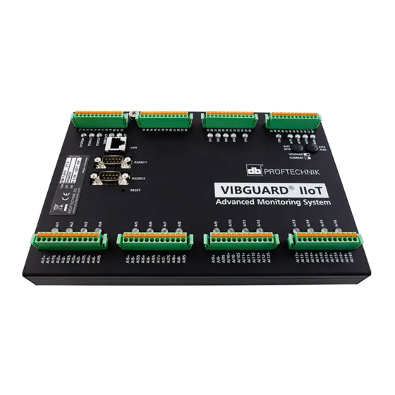
VIBGUARD
IIoT
Operation
Edition : 01.10.2018
Doc. no. : LIT 78.222.EN
Translation of the German manual
®
Type : VIB 7.800, VIB 7.810, VIB 7.811, VIB 7.815, VIB 7.820, VIB 7.825
Serial number and year of manufacture : see type plate
PRODUCER : Fluke Deutschland GmbH, Freisinger Str. 34, 85737
Ismaning, Germany, + 49 89 99616-0, www.pruftechnik.com
This manual is only intended for use with GL-
certified VIBGUARD CMS on wind turbines.
Advertisement
Table of Contents

Related Manuals for PRÜFTECHNIK FLUKE VIBGUARD IIoT


Summary of Contents for PRÜFTECHNIK FLUKE VIBGUARD IIoT
- Page 1 ® VIBGUARD IIoT Operation This manual is only intended for use with GL- certified VIBGUARD CMS on wind turbines. Type : VIB 7.800, VIB 7.810, VIB 7.811, VIB 7.815, VIB 7.820, VIB 7.825 Edition : 01.10.2018 Serial number and year of manufacture : see type plate Doc.
- Page 2 LEGAL NOTES Protection notice These instructions and the product described herein are protected by copyright. The authors reserve all rights. These instructions must not be copied, reproduced translated or made availa- ble to third parties in any other form - in part or in full - without prior approval. Exclusion of liability Any claims against the authors in relation to the product described in these instructions are excluded.
-
Page 3: Table Of Contents
Contents 1 Prior to starting 1.1 Notes regarding these instructions 1.2 Markup 1.3 Abbreviations 1.4 Service addresses 2 Safety 2.1 EU conformity 2.2 Intended use 2.3 Safety markings 2.4 Type plates 2.5 Information for the operator 2.6 Information for operating personnel 2.7 Residual hazards and protective measures 3 Control software 3.1 Hardware and software philosophy... - Page 4 9 Triggering a measurement manually 10 Data transmission by email 10.1 Configuring the E-Mail Center 11 Troubleshooting Edition: 10.2018...
-
Page 5: Prior To Starting
Operation 1 Prior to starting 1.1 Notes regarding these instructions These instructions are a part of the product. As such, they must be kept throughout the product service life. These instructions must be handed over to any subsequent owner or user of the product. 1.2 Markup Texts are marked as follows in these instructions: Action steps are indented and marked with a •... - Page 6 Empty page...
-
Page 7: Safety
Operation 2 Safety VIBGUARD IIoT was designed and built following careful selection of the harmonized norms to be complied with as well as other technical specifications. The system therefore corresponds to the state of the art and ensures the hig- hest degree of safety. -
Page 8: Safety Markings
Operation 2.3 Safety markings Please refer to the following figure for the safety markings on the VIBGUARD IIoT. The safety markings must be observed and must not be concealed or removed. For the variants that are installed in a control cabinet (VIB 7.xxx- PS), the safety labels must be attached at a suitable point in the control cabinet. -
Page 9: Type Plates
Operation 2.4 Type plates System module The type plate on the system module contains the following information: Type: Item number (VIB 7.820), hardware status (V1.3) of the System module. S/N: Serial number of the system module, 7 digits, starting with 95.. HW: Status (V 1.31), number (239), variant (LD = LineDrive) of the built-in board. -
Page 10: Information For The Operator
Operation 2.5 Information for the operator Obligations of the operator Maximum safety can only be achieved in practice if all measures required for this are adopted. As the operator, it is part of your duty of care to plan these measures and monitor their implementation. Ensure that the following requirements are met: Qualified specialist personnel for installation, commissioning and operation is available. -
Page 11: Information For Operating Personnel
Operation 2.6 Information for operating personnel Operating personnel qualifications Installation and disassembly may only be performed by a qualified specialist electrician. Commissioning and operation must only be performed by personnel who have been trained and authorized to do Personal protective equipment No protective equipment is required for installation, commissioning, normal operation and disassembly of the sys- tem. -
Page 12: Residual Hazards And Protective Measures
Operation 2.7 Residual hazards and protective measures VIBGUARD IIoT is verifiably safe assuming it is used as intended. The following damage may occur if operated incor- rectly or used improperly: Personal damage Damage to the system or to the machine Danger due to running machine! During installation and maintenance work on the machine, there is a risk of injury from moving machine com- ponents. -
Page 13: Control Software
Operation 3 Control software Executable real time software for controlling inputs and outputs, sequence control and visualization is already pre- installed on the VIBGUARD IIoT. The following software is required for further parameterization, data storage and analysis. The software is installed on a powerful PC: Email client OMNITREND Center 3.1 Hardware and software philosophy... -
Page 14: Programming Of The Control Software
Operation 3.2 Programming of the control software A real time operating system is installed on the VIBGUARD IIoT system. This operating system contains all of the func- tions for controlling the measuring components. A web server provides the HTML pages required for operation. These pages feature a series of parameterization, control and visualization masks. -
Page 15: Dialing Into The Cms
Operation 4 Dialing into the CMS Each VIBGUARD IIoT system has an IP address through which you can dial in from a PC. 4.1 Direct network connection (LAN) Use this option if the XP system or the PC are running in a common network or are connected to each other by means of a crossover network cable. -
Page 16: Dial-Up Connection
Operation 4.2 Dial-up connection If the CMS is connected via a router and dial-up connection, a PPP dial-up is required to establish the connection. Procedure for Windows 7 Open the Windows Start menu and select <Control Panel> / <Network and Sharing Center>. Select <Set up new connection ..>. -
Page 17: Connection Via A Vpn Tunnel
Operation 4.3 Connection via a VPN tunnel A VPN connection is required if the CMS is connected via a VPN network by means of an Internet router. There are a number of VPN software providers. Setup may vary depending on the software package used. Please contact the supplier in this regard. -
Page 18: Operation Via A Web Browser
Operation 5 Operation via a web browser VIBGUARD IIoT features a web server on which, inter alia, the user interface is implemented in the form of HTML pages. The HTML pages are only available in English. The functions for user inputs are provided via input boxes and buttons. This makes it possible to visualize mea- surement data, display alarm states and status messages, and archive data. -
Page 19: Alarm Status
Operation 6 Alarm status VIBGUARD IIoT provides an overview listing the current threshold violations and sensor errors. Opening the alarm status page Click on <System> in the navigation bar. Click on <Alarm Status Information> in the “Administration” field. The Alarm status page is displayed: The list contains all the measurement locations that exhibit a deviation from the normal condition in the current measurement cycle. -
Page 20: Displaying Readings
Operation 7 Displaying readings The current readings can be displayed in two views: Online readings Online readings and status Opening the views for the readings Click on <Online Visualisation> in the navigation bar. Click on <System Online ISL Table> in the "Input Storage Locations (ISLs)” field to open the Online readings view or on <Display Input Storage Location Values>... - Page 21 Operation "Online readings and status” view The Online readings and status view displays the current readings in all input memories and signalizes fault con- ditions by means of a colored background. The structure of the table is identical to the previous view (input memory number, label, reading, unit).
-
Page 22: Deleting Measurements
Operation 8 Deleting measurements You can delete signal data or the contents in the ring buffers if you have the requisite authorization. Note! Danger of data loss! Deleted data cannot be restored! 8.1 Deleting signal data With regard to signal data (DSP Data), you can delete all data in all subdirectories at once. Click on <Data Transfer>... - Page 23 Operation Deleting the ring buffers The storage concept of VIBGUARD IIoT is designed in such a way that the most up-to-date data is available even if the measurement data is not backed up at regular intervals. Automatically generated measurement data can be sto- red despite the memory being full.
- Page 24 Operation 9 Triggering a measurement manually You can manually trigger an additional diagnostic measurement at any time during the current measurement cycle. This type of measurement is configured in the OMNITREND Center software in the form of a diagnostics group and is linked to certain trigger conditions.
- Page 25 Operation 10 Data transmission by email For security reasons, the measurement data is transferred from VIBGUARD IIoT to an SMTP server at least once every 24 hours. The input of the measurement data into the OMNITREND Center database can be triggered directly from the PC software or, automatically, via the E-Mail Center program.
- Page 26 Operation Activate the Fetchmail function in the "E-Mail Center Administration" window (Enable). Create a new task (<Add>) or edit an existing task (<Edit>). The "Fetch Task" window appears. Enter a Name for the task. Enter the Server address ("External POP3 server") and, if necessary, activate the "SSL” option. Specify a Time interval for retrieving the data.
- Page 27 Operation If necessary, adjust the options and click on <OK>. Click on <OK> repeatedly to exit the configuration. VIBGUARD IIoT...
- Page 28 Operation 11 Troubleshooting The following errors may occur during operation: Symptom: Sensor status LED on the system module indicates a fault message (flashing orange). Possible cause: Sensor line is interrupted or has short circuited. Remedy: Check that the connections on the sensor and system are secure. Exchange any damaged cables Remedy: Check the cable connections with the PRÜFTECHNIK installation checker (item no.
- Page 29 Operation Possible cause: Supply voltage parameters out of specification. Remedy: Provide suitable supply voltage. Possible cause: No output voltage generated by power supply unit. Remedy: Replace power supply unit. Proceed as follows to remove the defective power supply unit: Push in the locking lever and pull the power supply unit (1T1) upwards. Possible cause: Unknown fault on the system module.
- Page 30 Printed in Germany LIT 78.222.EN.10.2018 Fluke Deutschland GmbH Freisinger Str. 34 85737 Ismaning, Germany + 49 89 99616-0 www.pruftechnik.com Productive Maintenance Technology...
Need help?
Do you have a question about the FLUKE VIBGUARD IIoT and is the answer not in the manual?
Questions and answers