Table of Contents
Advertisement
Advertisement
Table of Contents

Related Manuals for HBM T40MS


Summary of Contents for HBM T40MS
- Page 1 Mounting Instructions English T40MS HBM T40MS 2020 en (11.03.2020) HBM: public...
- Page 2 HBM T40MS 2020 en (11.03.2020) HBM: public...
-
Page 3: Table Of Contents
Supply voltage ............................27 6 Shunt signal ..................... 29 7 Functionality testing ................... 30 Rotor status, LED A (upper LED) ......................30 Stator status, LED B (lower LED) ......................31 8 Loading capacity ..................32 HBM T40MS 2020 en (11.03.2020) HBM: public... - Page 4 With speed measuring system ......................35 11.3 Adapter plate dimensions; for easy center alignment of former T11 applications ......36 12 Order numbers, accessories ..............37 13 Specifications .................... 38 14 Supplementary technical information ............42 HBM T40MS 2020 en (11.03.2020) HBM: public...
-
Page 5: Safety Instructions
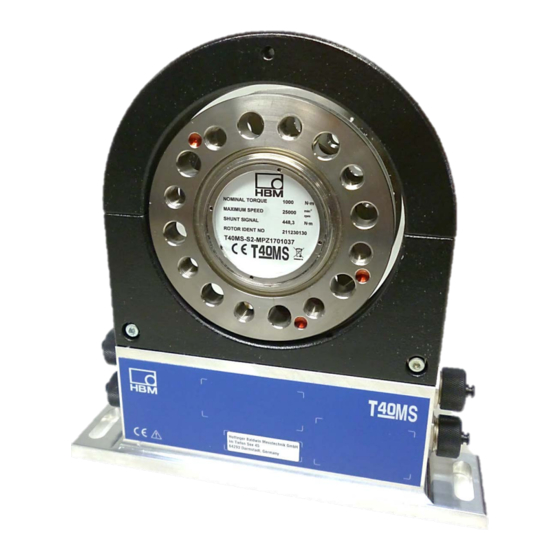
The FCC identifier or the unique identifier, as appropriate, must be displayed on the device. Model Rotor antenna Ø FCC ID T40S2 2ADAT-T40S2TOS6 12438A-T40S2TOS6 HBM T40MS 2020 en (11.03.2020) HBM: public... - Page 6 Label example with FCC ID and IC number Label Fig. 1.1 Location of the label on the stator of the device Fig. 1.2 Example of the label HBM T40MS 2020 en (11.03.2020) HBM: public...
- Page 7 Cet appareil est conforme aux normes d’exemption de licence RSS d’Industry Canada. Son fonctionnement est soumis aux deux conditions suivantes : (1)cet appareil ne doit pas causer d’interference et (2) cet appareil doit accepter toute interference, notamment les interferences qui peuvent affecter son fonctionnement. HBM T40MS 2020 en (11.03.2020) HBM: public...
- Page 8 It is also essential to observe the applicable legal and safety regulations for the application concerned. The same applies to the use of accessories. The T40MS torque flange is not intended for use as a safety component. Please also refer to the section "Additional safety precautions". Proper and safe operation requires proper transportation, correct storage, siting and mounting, and careful operation.
- Page 9 If the T40MS torque flange is not used according to the designated use, or if the safety instructions or specifications in the mounting and operating instructions are ignored, it is...
- Page 10 Selling on If the T40MS torque flange is sold on, these mounting instructions must be included with the T40MS torque flange. Qualified personnel Qualified personnel means persons entrusted with siting, mounting, starting up and operating the product, who possess the appropriate qualifications for their function.
-
Page 11: Markings Used
This marking draws your attention to information about the product or about Important handling the product. This marking indicates application tips or other information that is useful to you. HBM T40MS 2020 en (11.03.2020) HBM: public... -
Page 12: Application
Italics are used to emphasize and highlight texts . Application The T40MS torque flange measures static and dynamic torques on stationary and rotating shafts. Test beds can be extremely compact because of the short construction of the transducer. This offers a very wide range of applications. -
Page 13: Structure And Mode Of Operation
Structure and mode of operation The T40MS torque flange consists of two separate parts: the rotor and the stator. The rotor comprises the measuring body and the signal transmission elements. Strain gauges (SGs) are installed on the measuring body. The rotor electronics for transmitting the bridge excitation voltage and the measurement signal are located centrally in the flange. - Page 14 The magnet to be used for this is located on the inner surface of the flange. The sensor head for sampling the reference signal is located in the bracket above the rotational speed sensor. HBM T40MS 2020 en (11.03.2020) HBM: public...
-
Page 15: Mechanical Installation
• Comply with the mounting dimensions to enable correct operation. An appropriate shaft flange enables the T40MS torque flange to be mounted directly. It is also possible to mount a joint shaft or relevant compensating element directly on the rotor (using an intermediate flange when required). -
Page 16: Conditions On Site
With clockwise torque, the output frequency is, depending on the option, 60 - 90 kHz, 10 - 15 kHz or 240 - 360 kHz). With HBM amplifiers or with the voltage output option, a positive output signal (0 V -+10 V) is present. -
Page 17: Installation With Subsequent Stator Mounting
4.4.1 Installation with subsequent stator mounting 2. Install shaft train 1. Install rotor Washers Fan-type lock washers 3. Dismantle antenna segment 4. Install antenna segment Support supplied by customer 4. Mount support HBM T40MS 2020 en (11.03.2020) HBM: public... -
Page 18: Mounting The Rotor
Use a screw locking device (medium strength, e.g. LOCTITE No. 242) to glue the screws into the counter thread to exclude pre-stressing loss due to screw slackening, if alternating loads are to be expected. HBM T40MS 2020 en (11.03.2020) HBM: public... -
Page 19: Mounting The Stator
Antenna segment diameter 4.2 or Screws with washers 5.2mm, depending on (M5) maximum capacity Fan-type lock Antenna segments washers bottom Stator housing Fig. 4.1: Bolted connection of the antenna segments on the stator HBM T40MS 2020 en (11.03.2020) HBM: public... - Page 20 T40MS without speed measuring system T40MS with a rotational speed measuring system Sensor head for measuring rotational speed Stator housing Antenna wire lower antenna segment Fig. 4.2: Stator housing and lower antenna segment with antenna wire 1. Undo and remove the bolted connections (M5) on the upper antenna segment.
- Page 21 (zero index) is between the two flanges. Now tip the stator over the rotor until the antenna ring completely covers the flange with the transmitter winding (see Fig. 4.4, right). HBM T40MS 2020 en (11.03.2020) HBM: public...
- Page 22 Depending on the operating conditions, the stator may be excited to vibrate. This effect is dependent on: • The rotational speed • The antenna diameter (depends on the measuring range) • The design of the machine base HBM T40MS 2020 en (11.03.2020) HBM: public...
- Page 23 The cable plug also requires support in this case, a construction example is shown in Fig. 4.6. Fig. 4.5: Construction example for supporting the antenna ring Fig. 4.6: Construction example for connector terminals (for two connectors) HBM T40MS 2020 en (11.03.2020) HBM: public...
-
Page 24: Speed Measuring System, Reference Pulse
In applications where magnetic strengths are expected to be high (such as an eddycurrent brake), suitable action must be taken to ensure that the max. magnetic field strength stated in the specification is not exceeded. HBM T40MS 2020 en (11.03.2020) HBM: public... - Page 25 Sensor head for measuring Never loosen the screws! rotational speed Fig. 4.8: Torque transducer with sensor head for rotational speed measurement HBM T40MS 2020 en (11.03.2020) HBM: public...
-
Page 26: Electrical Connection
• All plug connections or swivel nuts must be fully tightened . Important Transducer connection cables from HBM with attached connectors are identified in accordance with their intended purpose (Md or n). When cables are shortened, inserted into cable ducts or installed in control cabinets, this identification can get lost or become concealed. - Page 27 Electrical and magnetic fields often induce interference voltages in the measuring circuit. Therefore: • Use shielded, low-capacitance measurement cables only (HBM cables fulfill both conditions). • Only use plugs that meet EMC guidelines. • Do not route the measurement cables parallel to power lines and control circuits.
-
Page 28: Connector Pin Assignment
Shielding connected to housing ground Bridge between 4 + 9 RS-422 complementary signals; with cable lengths exceeding 10 m, we recommend using a termination resistor R = 120 ohms between the (wh) and (rd) wires. HBM T40MS 2020 en (11.03.2020) HBM: public... - Page 29 Bridge between 4 + 9 RS-422 complementary signals; with cable lengths exceeding 10 m, we recommend using a termination resistor R = 120 ohms between the (wh) and (rd) wires. KAB163/KAB164: color code brown (bn) HBM T40MS 2020 en (11.03.2020) HBM: public...
- Page 30 . 5. tati s at plug 2 (rotational speed in the direction of the arrow) Fig. 5.2: Rotational speed signals at plug 2 (rotational speed against the direction of the arrow) HBM T40MS 2020 en (11.03.2020) HBM: public...
-
Page 31: Supply Voltage
The transducer is operated with a separated extra-low voltage (nominal (rated) supply voltage 18 - 30 VDC). You can supply one or more T40MS torque flanges simultaneously within a test bench. Should the device be operated on a DC voltage network ) , additional precautions must be taken to discharge excess voltages. - Page 32 We recommend that you use HBM cable KAB 8/00-2/2/2 and appropriate sockets (see Accessories). The cable can be up to 50 m long for voltages >=24 V, otherwise it can be up to 20 m long. If the permissible cable length is exceeded, you can supply the voltage in parallel over two connection cables (connectors 1 and 3).
-
Page 33: Shunt Signal
After activation, adjust the amplifier output signal to the shunt signal supplied by the connected transducer to adapt the amplifier to the transducer. The shunt signal can be triggered by the amplifier or via the operating software in HBM system solutions. -
Page 34: Functionality Testing
The measurement signals reflect the level of the defect status. Pulsating means that the LED goes dark for about 20 ms every second ( sign of life); making it possible to detect that the transducer is functioning. HBM T40MS 2020 en (11.03.2020) HBM: public... -
Page 35: Stator Status, Led B (Lower Led)
Orange (permanently lit) => Correct the rotor/stator alignment. Internal stator defect, the measurement signals reflect the level of the defect (permanently lit) status (f out = 0 Hz, U out = defect level). HBM T40MS 2020 en (11.03.2020) HBM: public... -
Page 36: Loading Capacity
"Specifications" (Chapter 13, Page 34). Measuring dynamic torque The T40MS torque flange can be used to measure static and dynamic torques. The following rule applies to the measurement of dynamic torque: • The transducer calibration performed for static measurements is also valid for dynamic torque measurements. -
Page 37: Maintenance
Packaging The original packaging of HBM devices is made from recyclable material and can be sent for recycling. Store the packaging for at least the duration of the warranty. In the case of complaints, the T40MS torque flange must be returned in the original packaging. -
Page 38: Dimensions
11 Dimensions 11.1 Without speed measuring system HBM T40MS 2020 en (11.03.2020) HBM: public... -
Page 39: With Speed Measuring System
11.2 With speed measuring system HBM T40MS 2020 en (11.03.2020) HBM: public... -
Page 40: Adapter Plate Dimensions; For Easy Center Alignment Of Former T11 Applications
11.3 Adapter plate dimensions; for easy center alignment of former T11 applications HBM T40MS 2020 en (11.03.2020) HBM: public... -
Page 41: Order Numbers, Accessories
423G-7S, 7 pin (straight) 3-3101.0247 423W-7S, 7 pin (angle) 3-3312.0281 423G-8S, 8-pin (straight) 3-3312.0120 423W-8S, 8 pin (angle) 3-3312.0282 Connection cable, by the meter (minimum order quantity: 10 m, price per meter) Kab8/00-2/2/2 4-3301.0071 HBM T40MS 2020 en (11.03.2020) HBM: public... -
Page 42: Specifications
< ± 0.03 Frequency output < ± 0.03 Voltage output Measurement frequency range ( -3dB ) Group delay µs < 400 / < 220 / < 150 Residual ripple < 40 Voltage output HBM T40MS 2020 en (11.03.2020) HBM: public... - Page 43 Axial nominal (rated) distance between sensor head and magnetic ring (mechanical distance) Workling distance range between sensor head and 3 to 4 magnetic ring Max. permissible axial displacement of rotor to ± 0,5 stator HBM T40MS 2020 en (11.03.2020) HBM: public...
- Page 44 (rated) torque. The load limits only apply for the nominal (rated) temperature range. At temperatures <10”C, load limits are expected to reduce by up to 30%, because the strength reduction increases as the temperatures fall. 13) With a static loading. 14) Static and dynamic. 15) The nominal (rated) torque must not be exceeded. HBM T40MS 2020 en (11.03.2020) HBM: public...
- Page 45 (rotational acceleration max. 20.000rad/s • Special torque transducers of type T40MS which will be used under „Formula 1“ conditions have a limited warranty of 250 working hours. Afterwards we recommend replacing the sensor.
-
Page 46: Supplementary Technical Information
500-2k 0.01 0.01 To ensure that the T40MS torque flange retains its characteristics once it is installed, we recommend that the customer also chooses the specified form and position tolerances, surface quality and hardness for the connections provided. HBM T40MS 2020 en (11.03.2020) - Page 47 HBM T40MS 2020 en (11.03.2020) HBM: public...
- Page 48 Sinne des §443 BGB dar und begründen keine Haftung. Hottinger Baldwin Messtechnik GmbH Im Tiefen See 45 • 64293 Darmstadt • Germany Tel. +49 6151 803-0 • Fax: +49 6151 803-9100 Email: info@hbm.com • www.hbm.com HBM T40MS 2020 en (11.03.2020) HBM: public...
Need help?
Do you have a question about the T40MS and is the answer not in the manual?
Questions and answers