Table of Contents
Advertisement
Quick Links
Advertisement
Table of Contents

Related Manuals for Octek HIPPO DCA 2


Summary of Contents for Octek HIPPO DCA 2
- Page 1 USER'S MANUAL HIPPO DCA 2 VESA LOCAL BUS MOTHERBOARD...
- Page 2 Hippo DCA2 486 486 VESA Local Bus Motherboard User’s Manual Version 2.25 December 1994...
- Page 3 MR BIOS is a trademark of Microid Research, Inc. Novell is a registered trademark of Novell, Inc. Octek is a registered trademark of Ocean Information Systems, Inc. OPTi is a registered trademark of OPTi Inc. Unix is a registered trademark of American Telephone and Telegraph Company Bell Laboratories.
- Page 4 Technical information is also included in the Appendix for hardware and software engineers. This manual provides information about the installation and maintenance of the Octek Hippo DCA2 motherboard. In-depth explanations concerning the functions and features of this motherboard are provided.
-
Page 5: Table Of Contents
Table of Contents Preface....................iii Chapter 1: DCA2 System Overview What is DCA2 ? ....................1 What makes DCA2 so powerful ?...............1 What is DynamiCache ? ..................1 Why is DCA2 a better choice ? ................1 User advantages of DCA2...................2 Technical advantages of DCA2................2 DynamiCache Description ..................3 DynamiCache Architecture ................3 Distributed Cache ....................4... - Page 6 Chapter 3: Setup and Installation Setup ........................16 Installation Precautions ..................16 Operation and Maintenance ................16 CPU Jumper Settings ..................17 CPU Installation ....................18 DynamiCache / DRAM Installation ..............19 Compatible 72-pin SIMM Types ..............20 Control of System Speeds .................21 Fan Voltage.......................21 3.10 Fan connector ....................21 3.11 Reset CMOS buffer ...................21 3.12 Color / Mono display select.
-
Page 7: Chapter 1: Dca2 System Overview
Chapter 1 System Overview CHAPTER 1 SYSTEM OVERVIEW Listed below are answers to some questions you may have about DCA2 and its phenomenal performance. What is DCA2 ? DCA2 (DynamiCache Architecture - 2nd generation) is a high performance cache memory system that alleviates the traditional bottleneck of mainboards. -
Page 8: User Advantages Of Dca2
Chapter 1 System Overview memory operates at the same speed as the CPU, allowing the CPU to retrieve instructions from any location within the main memory at zero wait states. Users advantages of DCA2 The entire memory bank acts as if its a cache subsytem. ... -
Page 9: Dynamicache Architecture
Chapter 1 System Overview DynamiCache Architecture The DynamiCache chips are physically similar to a standard 4MB page mode or static column DRAM with the addition of an integrated Row Register Register and an internal controller that allows it to operate much like page mode or static column DRAM. DynamiCache’s Row Register register is tightly coupled with the Memory Array. -
Page 10: Distributed Cache
Chapter 1 System Overview Distributed Cache DynamiCache uses what is referred to as distributed cache rather than lumped cache. The 15 ns access time is available throughout the entire range of installed DynamiCache, not just in a small external cache. External cache only provides benefit to the system while the instructions are housed in the cache. -
Page 11: External Cache Saturation Problem
Chapter 1 System Overview is large enough, the L2 cache is kept filled with data on a continuous basis. It is the maintenance of this traffic flow that dramatically reduces the amount of time the CPU would otherwise have for executing software instructions. 1.13 Dynamicache Excels and External Cache Suffers Under Heavy Processing Loads... -
Page 12: L2/ Dca2 Cache Efficiency Versus Application Size
Chapter 1 System Overview 1.15 L2/ DCA2 Cache Efficiency Versus Application Size Where do the software applications fit on this curve ? ⚫ Typical Benchmarks usually utilize less than 5% memory load. ⚫ DOS applications typically generate less than 25% memory load. ⚫... -
Page 13: General Specifications Overview
Chapter 1 System Overview 1.16 General Specifications Overview Processor: Processor Type Intel 486SX-25/33, 486DX-25/33, 486DX2-50/66 Intel 486DX4-75/100, Intel P24T AMD 486DX-40, 486DX2-50/66 Cyrix 486DX-33, 486DX2-50/66 Speed 25 / 33 / DX2-50 / DX2-66 / DX4-100 CPU voltage detection Automatic voltage conversion circuitry Cache Architecture: ... -
Page 14: Chapter 2: Features
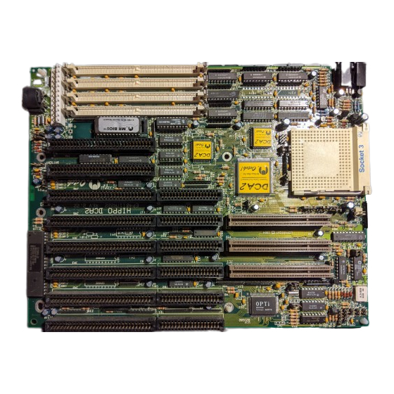
Chapter 2 General Features CHAPTER 2 GENERAL FEATURES Layout of Hippo DCA2 Board Figure 2 Inspect and clean your computer system regularly. Electronic components are sensitive to dust and dirt. Hippo DCA2 User’s Manual... -
Page 15: System Component Map
Chapter 2 General Features System Component Map M e m o r y / S y s t e m C o m p o n e n t s Keyboard BIOS Keyboard connector Power connector 8-Bit ISA slots 16-Bit ISA Extension slots 32-Bit VESA Extension slots DynamiCache slot-1 and slot-2 DRAM slot-1 and slot-2... -
Page 16: Jumper Description Table
Chapter 2 General Features Jumper Description Table Jumper Description Setting Option Fan voltage select (+12/+5V) +12V Fan connector <RFU> CPU clock speed select 25 Mhz 33 MHz CPU clock speed select 25 Mhz 33 MHz CPU reset signal source <RFU> CPU initialization signal source open Cyrix, SL... -
Page 17: Dynamicache
Chapter 2 General Features DynamiCache The DynamiCache memory subsystem consists of two 72-pin DynamiCache SIMM sockets. These sockets support up to 32MB of DynamiCache configured in 4MB, 8MB, and 16MB modules. (16MB to be released Q2 1995). The DynamiCache sockets are located on the top right corner of the motherboard. -
Page 18: Memory Configuration Table
Chapter 2 General Features Memory Configuration Table Bank 0 Bank 1 Bank 2 Bank 3 DynamiCache DynamiCache DRAM DRAM Total Memory Slot 1 Slot 2 Slot 1 Slot 2 Size 16 * * 16MB DynamiCache Module scheduled to be released Q2, 1995 Hippo DCA2 User’s Manual... -
Page 19: Total System Memory
Chapter 2 General Features Total System Memory The entire main memory is composed of the total DynamiCache plus DRAM subsystem. Refer to the chart below for possible memory configurations, from 4MB to 32MB. The system auto detects the memory size. For maximum efficiency in system performance, OISI strongly recommends a minimum of 8MB DynamiCache. -
Page 20: Cpu
Chapter 2 General Features The 32-bit data path VESA Local Bus provide a direct link between the CPU and the system memory, allowing data to be processed at the speed of the CPU, up to 33MHz, rather than the slower running 16-bit at 8-12 Mhz data path ISA BUS rate. Figure 6 2.10 The Central Processing Unit (CPU) is the part of the computer that interprets and executes... -
Page 21: Shadow Ram
Chapter 2 General Features 2.13 Shadow RAM Shadow RAM improves computer performance by taking data that is stored in ROM (read - only memory) and copying the information into the much faster RAM (random-access memory). The control setup for the Shadow RAM is located in the configuration registers. 2.14 Power Management The Hippo DCA2 supports Green Functions, which make the system fully compliant with... -
Page 22: Chapter 3: Setup And Installation
Chapter 3 Setup and Installation CHAPTER 3 SETUP AND INSTALLATION Setup Before installing the Hippo DCA2 motherboard in your system, you must attach the peripheral connectors. Follow the instructions outlined in this chapter for proper installation. Installation Precautions • Turn off the power whenever installing or removing any connectors, memory module or add- on cards. -
Page 23: Cpu Jumper Settings
Chapter 3 Setup and Installation CPU Jumper Settings Brand Type JP10 JP11 JP13 JP14 JP15 Intel SX-25 open open open Intel SX-33 open open open Intel DX-25 open open 1-2, 3-4 Intel DX-33 open open 1-2, 3-4 Intel DX2-50 open open 1-2, 3-4 Intel *... -
Page 24: Cpu Installation
Chapter 3 Setup and Installation CPU Installation The CPU is composed of several pins that can easily be bent during installation, causing permanent damage to the processor. It is therefore very important that you make sure the pins are straight before installing the CPU onto the PGA socket located on your motherboard (refer to layout for exact location). -
Page 25: Dynamicache/Dram Installation
Chapter 3 Setup and Installation DynamiCache/DRAM Installation There are four memory banks located on the Hippo motherboard, marked DynamiCache Bank DynamiCache Bank 2, DRAM Bank 1, DRAM Bank 2. The DynamiCache modules must be inserted into theDynamiCache banks and the DRAM modules into the DRAM banks. -
Page 26: Compatible 72-Pin Simm Types
Chapter 3 Setup and Installation To insert the modules into the banks follow these steps: 1. Locate the notch on the corner of the module. 2. Hold the module so that the notch is at the bottom left corner. 3. Insert the bottom edge of the module into the bank at an angle, then push the module forward so that it is locked into place by the latches located on the sides of the bank. -
Page 27: Control Of System Speeds
Chapter 3 Setup and Installation Control of System Speed System speed can be controlled by keyboard and turbo switch. To change the speed by keyboard, use the minus sign (-) and the plus sign (+). Press <control> + <alt> + <“-”> for slow speed and <control>... -
Page 28: Color / Mono Display Select
Chapter 3 Setup and Installation 3.12 Color / Mono Display Select Depending on the type of monitor you are using. Set jumper JP21 to 1-2 for a color display monitor ( which includes all types of VGA monitors ), and set jumper JP21 to 2-3 for a monochrome display monitor. -
Page 29: Turbo Led Connector
Chapter 3 Setup and Installation 3.15 Turbo Switch Connector The turbo switch connector is a two-pin single in-line berg that is attached by cable to an externally mounted turbo switch on the chasis. The turbo button is used to toggle between standard AT-Bus speed and maximum speed of the processor. -
Page 30: Speaker Connector
Chapter 3 Setup and Installation 3.17 Speaker Connector The speaker connector is a four-pin berg that is attached via a cable to the system speaker. This is a nonpolarized connector and can be installed in keyed position. Description Data Out Ground Figure 14 3.18... -
Page 31: Keyboard Connector
Chapter 3 Setup and Installation 3.19 Keyboard Connector The keyboard connector is a five-pin DIN socket. Attach a standard AT-compatible keyboard cable. The pin assignments are listed below. Assignment Keyboard clock Keyboard data Not used Ground Figure 16 Turn off the power whenever installing or removing any connector, memory module or add-on cards. - Page 32 Chapter 3 Setup and Installation 3.21 Power Supply Connector The power supply is the electrical device that converts the alternating current used by standard A C outlets to the lower-voltage direct current required by computers. A stable power source is essential for proper and reliable operation. It is therefore a good idea to use a high quality power supply.
-
Page 33: Chapter 4: Bios Setup
Chapter 4 Bios Setup CHAPTER 4 BIOS SET UP BIOS Power-On Self-Test (POST) During the self-test, errors may occur. These errors are communicated through a series of beeps. The method of beeps used depends on the BIOS program. For example, Microid Research BIOS uses a combination of low and high tones. - Page 34 Chapter 4 Bios Setup Beep Tones Error Message L H L H H Real time clock is not updating L H-L L L ROM BIOS checksum test L H-H L L Page register test L H-L H L Keyboard controller self-test L H-H H L Memory refresh circuit test L H-L L H...
-
Page 35: Appendix: Advanced Technical Information
Appendix Advanced Technical Information APPENDIX ADVANCED TECHNICAL INFORMATION Memory Address Map Address Size Function 0000000-009FFFF 640 KB System board memory 00A0000-00BFFFF 128 KB Video RAM display buffer 00C0000-00DFFFF 128 KB Reserved for add-on cards ROM BIOS 00E0000-00EFFFF 64 KB System ROM BIOS expansion 00F0000-00FFFFF 64 KB System ROM BIOS... -
Page 36: I/O Address Map
Appendix Advanced Technical Information I/O Address Map I/O Address Hex 000 to 0FF are reserved for the system board and Hex 100 to 3FF are for I/O channels. Address (Hex) Device 000-01F DMA Controller 1, 8237A-5 020-021 Interrupt Controller 1, 8237A-5 022-023 Chip set Address 040-04F... -
Page 37: I/O Extension Pinout
Appendix Advanced Technical Information I/O Extension Pinout A.3i 8-Bit ISA Pinout Ground -I/O CHCK RSTDRV Power +5 VDC IRQ9 Power -5 VDC DRQ2 Power -12 VDC Power +12 VDC Ground -I/O CHRDY -SMEMW -SMEMR SA19 -IOW SA18 -IOR SA17 -DACK3 SA16 DRQ3 SA15... -
Page 38: Direct Memory Access Channels
Appendix Advanced Technical Information Ground Ground CD11 CD10 CD13 CD12 CD15 Power Ground CD14 CD17 CD16 Power CD18 CD19 CD20 CD21 Ground CD23 CD22 CD25 CD24 Ground CD26 CD27 CD28 CD29 CD30 CD31 Power CA30 CA31 CA28 Ground CD26 CA29 Ground CA27 CA24... -
Page 39: Dma Controller Registers
Appendix Advanced Technical Information Block Size Spare 8-bit SDLC 8-bit Floppy Disk 8-bit Spare 8-bit Cascade for DMA controller 1 Spare 16-bit Spare 16-bit Spare 16-bit DMA Controller Registers Address (Hex) Command Code CH-0 base and current address CH-0 base and current word count CH-1 base and current address CH-1 base and current word count CH-2 base and current address... -
Page 40: Page Register Address
Appendix Advanced Technical Information Page Register Address Page Register I/O Address (Hex) DMA Channel 0 0087 DMA Channel 1 0083 DMA Channel 2 0081 DMA Channel 3 0082 DMA Channel 5 008B DMA Channel 6 0089 DMA Channel 7 008A Refresh 008F System Interrupts...
Need help?
Do you have a question about the HIPPO DCA 2 and is the answer not in the manual?
Questions and answers