Table of Contents
Advertisement
Quick Links
Advertisement
Table of Contents

Related Manuals for Octek Panther II


Summary of Contents for Octek Panther II
- Page 1 P A N T H E R - I I...
- Page 2 The material in this manual is for information only and is subject to change without notice. REVISION : 1.0 IBM, IBM PC/XT/AT, PC-DOS, MS-DOS, OS/2, UNIX, XENIX, MR BIOS, AMI BIOS, INTEL, 386SX, 386 and 286 ARE THE TRADEMARKS OR REGISTERED TRADEMARKS OF THEIR RESPECTIVE OWNERS.
- Page 3 RADIO FREQUENCY INTERFERENCE STATEMENT This equipment generates and uses radio frequency energy and if not installed and used properly, that is, in strict accordance with the manufacturer's instructions, may cause interference with radio and television reception. If this equipment does cause interference to radio or TV reception, which can be determined by turning the equipment off and on, the user is encouraged to try to correct the interference by one or more of the following measures :...
- Page 4 Note Be certain that the BIOS Setup is properly initialized before actual operation, otherwise performance degrade and/or reliability problem may result. a)For optimum performance, select "0 W/S" for DRAM Read & Write Wait State under the "Advanced Chipset Setup" of the BIOS Setup Utility.
- Page 5 Preface This manual covers the necessary information to operate the Panther-II system board. In-depth explanations of the functions of the motherboard are provided. The table of contents gives detailed information about the arrangement of this manual. The system BIOS setup is further discussed in the appendix. The content in this manual is only for reference and is intended to provide basic information for the general users.
-
Page 6: Table Of Contents
CONTENT Chapter 1 INTRODUCTION Chapter 2 GENERAL FEATURES Specification Processor Math Coprocessor Memory System I/O Subsystem 2-11 System Functions 2-12 Chapter 3 INSTALLING COMPONENTS 3-1 Installing 80387SX Math Coprocessor System Memory Configuration Control of System Speed System Board Jumper Setting 3-10 System Board Connectors 3-11... - Page 7 Chapter 4 TECHNICAL INFORMATION 4-1 Memory Mapping I/O Address Map System Timers System Interrupts Direct Memory Access (DMA) Real Time Clock and CMOS RAM CMOS RAM Address Map 4-10 Real Time Clock Information 4-11 System Expansion Bus 4-12 APPENDIX A SYSTEM BIOS Self-Test System Setup...
-
Page 9: Chapter 1 Introduction
Chapter 1 Introduction _______________________________ The Panther-II system board is a high performance system board that represents a significant technological advance over the conventional 386SX designs. It offers an increased power and flexibility architecture by supporting 80386SX processor speeds up to 25 Mhz (See NOTE on preface). - Page 10 INTRODUCTION __________________________________ The Panther-II is a fully PC/AT compatible system board implemented with a highly integrated chip sets to provide high performance, reliability and compatibility. It is based on the 386SX CPU which can access the world's largest existing microcomputer software base, including the growing 32-bit software.
- Page 11 INTRODUCTION __________________________________ THIS PAGE IS INTENTIONALLY LEFT BLANK...
-
Page 13: General Features
Chapter 2 General Features _______________________________ SPECIFICATION Processor Subsystem : Intel 80386SX CPU Optional 80387SX Co-processor Speed : Turbo/normal speed Software/hardware selectable Memory Subsystem : 16MB maximum using 4M SIMMs 2MB using 256Kbx4 DRAM chips Page/Interleave memory: Page mode memory 2-way and 4-way interleave mode System BIOS shadow Video BIOS shadow Parity Check option... - Page 14 GENERAL FEATURES __________________________________ I/O Subsystem : Compatible to standard AT bus Four 16-bit expansion slots Two 8-bit expansion slots System Support Functions : -8-Channel DMA (Direct Memory Access) -16-level interrupt -3 programmable timers -CMOS RAM for system configuration -Real time clock with battery backup -OS/2 Optimization (Fast A20 gate and fast reset) Other Features : -On board POWERGOOD test circuit...
-
Page 15: Processor
GENERAL FEATURES __________________________________ PROCESSOR The 80386SX Microprocessor is a 32-bit CPU with a 16-bit external data bus and a 24-bit external address bus. The 386SX CPU brings the high-performance software of the Intel386 Architecture to mid-range systems. It provides the performance benefits of a 32-bit programming architecture with the cost saving associated with 16-bit hardware systems. - Page 16 GENERAL FEATURES __________________________________ very important attribute of any multi-tasking/multi-user operating system is its ability to rapidly switch between tasks or processes. The 386SX Microprocessor directly supports this operation by providing a task switch instruction in hardware. The 386SX Microprocessor has two modes of operation: Real Address Mode (Real Mode), and Protected Virtual Address Mode (Protected Mode).
-
Page 17: Math Coprocessor
GENERAL FEATURES __________________________________ MATH COPROCESSOR The demand for sophisticated, number-crunching scientific and business applications has rapidly increased in recent years. 80386SX features an integer Arithmetic Logic Unit which only handles simple integer operations such as addition and multiplication. Floating-point operations which are actually utilized by applications must be accomplished through software routines. - Page 18 GENERAL FEATURES __________________________________ 387DX and upward object code compatible from the 80287 and 8087 Math Co-processors. In real-address mode and virtual-8086 mode, the 386SX Microprocessor and 387SX Math Coprocessor is completely upward compatible with software for the 8086/8087 and 80286/80287 real-address mode systems.
-
Page 19: Memory System
GENERAL FEATURES __________________________________ MEMORY SYSTEM Panther-II supports the use of 256K, 1M and 4M DRAMs device configurations for up to 16MB of on-board system memory. Both page mode and interleave operation are incorporated on the system board DRAM. Page mode is enabled or disabled for each pair of DRAM banks independently. - Page 20 GENERAL FEATURES __________________________________ Automatic Interleave vs Memory Map Bank Bank A Bank Address Mode B Bank Address Mode Yes No Linear No N/A Yes Yes 2-Way Interleave No N/A Yes Yes 2-Way Interleave No Linear Yes Yes 2-Way Interleave 0 and 1* Yes Yes 2-Way Interleave 2 and 3* *This is for the case where Banks A and B contain different types of DRAMS.
- Page 21 GENERAL FEATURES __________________________________ supported. Shadow RAM is a technique that loads system BIOS ,video and/or adapter BIOS from the low speed EPROM/ROM directly into fast DRAM during boot-up of the computer. The execution of the BIOS then will have significant improvement because access to DRAM is much faster than ROM.
-
Page 22: I/O Subsystem
GENERAL FEATURES __________________________________ I/O SUBSYSTEM It is very important that a high speed system should be compatible with existing peripherals without downgrading the performance. The Panther-II system is exactly designed with this capability in mind. To be compatible with the existing add-on cards, user has the option of defining the I/O speed. -
Page 23: System Functions
GENERAL FEATURES __________________________________ SYSTEM FUNCTIONS System functions include : - Interrupt - DMA - Timer - Real time clock - Clock and ready generation - I/O channel control All system functions are 100% compatible to AT standard. I/O channel of Panther-II is designed to be compatible with standard AT bus. All the expansion cards conformed to the standard AT bus can be used in Panther-II without problem. -
Page 25: Installing Components
Chapter 3 Installing Components _______________________________ Warning : Be sure to turn off the computer's power switch before installing or replacing any component. If installation sounds risky, let your dealer install the 80387SX. If you make a mistake, you could damage the 80387SX or your computer. INSTALLING 80387SX MATH COPROCESSOR Math coprocessor 80387SX is available in a 68-pin PLCC package. - Page 26 INSTALLING COMPONENTS __________________________________...
-
Page 27: System Memory Configuration
INSTALLING COMPONENTS __________________________________ SYSTEM MEMORY CONFIGURATION Four DIP memory banks and two SIMM memory banks are available on Panther-II, these memory banks are designated as BANK 0 to BANK 3 in the motherboard. User has the option of either using DIP type DRAM or SIMM type memory modules. - Page 28 INSTALLING COMPONENTS __________________________________ DIP DRAM Memory Organization Memory Bank DIP Memory Location DRAM Size BANK 0 U39, U40, U41, U42 44256 U38, U37 (parity) 41256 BANK 1 U33, U34, U35, U36 44256 U32, U30 (parity) 41256 BANK 2 U26, U27, U28, U29 44256 U31, U24 (parity) 41256...
- Page 29 INSTALLING COMPONENTS __________________________________ The different configurations of memory is illustrated in the next table. It shows the page mode, interleave options and the DRAM combinations available for each possible memory map. Since interleaving requires pairs of banks, various controls described act on memory in bank pairs.
- Page 30 INSTALLING COMPONENTS __________________________________ Installing SIMM Modules Whenever adding memory modules to the motherboard, install 2 modules at a time. Also make sure that the SIMM is installed in the correct orientation, the RAM chips on the modules should be facing the I/O slot.
- Page 31 INSTALLING COMPONENTS __________________________________ RAM Module Orientation...
-
Page 32: Control Of System Speed
INSTALLING COMPONENTS __________________________________ CONTROL OF SYSTEM SPEED System speed can be selected by hardware switch and keyboard. Connector P3 should be connected to the turbo switch of the case panel, this toggles the operation mode between turbo and normal mode when pressed. -
Page 33: System Board Jumper Setting
INSTALLING COMPONENTS __________________________________ SYSTEM BOARD JUMPER SETTING There are a few jumpers in the motherboard that allow the user to select the desired system configuration. The following tables show the function and default settings of these jumpers. Display Selection Display Type Monochrome Display * CGA, EGA, VGA, PGA Default setting... - Page 34 INSTALLING COMPONENTS __________________________________ `CMOS Setup' Reset Jumper Sometimes, improper setup may cause the system to malfunction and you might not be able to correct such problem without clearing the entire CMOS Setup. The purpose of this jumper is for the user to reset the CMOS Setup in case of critical error occurred in the Setup.
-
Page 35: System Board Connectors
INSTALLING COMPONENTS __________________________________ SYSTEM BOARD CONNECTORS Under typical conditions, these connectors should be connected to the indicators and switches of the system unit. Connector Function Hardware reset connector Speaker connector Turbo switch connector Turbo LED connector Power LED & Ext-Lock connector P6-P7 Power supply connector External battery connector... - Page 36 INSTALLING COMPONENTS __________________________________ P 2 - Speaker Connector Assignment Data out +5 Vdc Ground +5 Vdc P 3 - Turbo Switch Connector Assignment Selection Pin Ground P 4 - Turbo LED Connector Assignment +5 Vdc LED signal 3-12...
- Page 37 INSTALLING COMPONENTS __________________________________ P 5 - Power LED & Ext-Lock Connector Assignment +5 Vdc Ground Keyboard inhibit Ground P6-P7 - Power Supply Connector Assignment POWERGOOD +5 Vdc +12 Vdc -12 Vdc Ground Ground Assignment Ground Ground -5 Vdc +5 Vdc +5 Vdc 3-13...
- Page 38 INSTALLING COMPONENTS __________________________________ +5 Vdc P 8 - External Battery Connector Assignment + Vdc not used Ground Ground KB 1 - Keyboard Connector Assignment Keyboard clock Keyboard data Spare Ground +5 Vdc 3-14...
-
Page 39: Technical Information
Chapter 4 Technical Information _______________________________ This section provides technical information about Panther-II and is intended for advanced users interested in the basic design and operation of Panther-II. MEMORY MAPPING Address Range Function 000000-7FF 000K-512K System Board Memory (512K) 080000-09F 512K-640K System Board Memory (128K) 0A0000-0B 640K-768K... -
Page 41: I/O Address Map
TECHNICAL INFORMATION __________________________________ I/O ADDRESS MAP I/O Address Map on System Board I/O address hex 000 to 0FF are reserved for the system board I/O. ADDRESS DEVICE (HEX) 000-01F DMA Controller 1, 8237 020-03F Interrupt Controller 1, 8259, Master 040-05F Timer, 8254 060-06F Keyboard Controller... - Page 42 TECHNICAL INFORMATION __________________________________ I/O address hex 100 to 3FF are available on the I/O channel. ADDRESS DEVICE (HEX) 1F0-1F8 Fixed Disk 200-207 Game I/O 278-27F Parallel Printer Port 2 2F8-2FF Serial Port 2 300-31F Prototype Card 360-36F Reserved 378-37F Parallel Printer Port 1 380-38F SDLC, bisynchronous 2 3A0-3AF...
-
Page 43: System Timers
TECHNICAL INFORMATION __________________________________ SYSTEM TIMERS Panther-II has three build-in programmable timer/counters defined as channels 0 through 2 : Channel 0 System Timer Gate 0 Tied on Clk in 0 1.190 Mhz OSC Clk out 0 8259 IRQ 0 Channel 1 Refresh Request Generator Gate 1... - Page 44 TECHNICAL INFORMATION __________________________________ Note :Channel 1 is programmed to generate a 15-micro-second period signal.
- Page 45 TECHNICAL INFORMATION __________________________________ The 8254 Timer/Counters are treated by system programs as an arrangement of four programmable external I/O ports. Three are treated as counters and the fourth is a control register for mode programming.
-
Page 46: System Interrupts
TECHNICAL INFORMATION __________________________________ SYSTEM INTERRUPTS Sixteen levels of system interrupts are provided on Panther-II. The following shows the interrupt-level assignments in decreasing priority. ┌──────────────────────────────────────┐ Level Function Microprocessor NMI Parity or I/O Channel Check Interrupt Controllers CTLR 1 CTLR 2 IRQ0 Timer Output 0 IRQ1 Keyboard... - Page 47 TECHNICAL INFORMATION __________________________________ │ │ │ │ ╞══════════════════════════════════════╡ │ │ │ │ │ │ │ │ │ │ │ │ │ │ │ ─┐ │ │ │ ┌─ │ │ │ │ │ │ │ │ │ │ │ │ │...
-
Page 48: Direct Memory Access (Dma)
TECHNICAL INFORMATION __________________________________ DIRECT MEMORY ACCESS (DMA) Panther-II supports seven DMA channels. Channel Function Spare (8 bit transfer) SDLC (8 bit transfer) Floppy Disk (8 bit transfer) Spare (8 bit transfer) Cascade for DMA Controller 1 Spare (16 bit transfer) Spare (16 bit transfer) Spare (16 bit transfer) 4-10... - Page 49 TECHNICAL INFORMATION __________________________________ The following shows the addresses for the page register. Page Register I/O Address (HEX) DMA Channel 0 0087 DMA Channel 1 0083 DMA Channel 2 0081 DMA Channel 3 0082 DMA Channel 5 008B DMA Channel 6 0089 DMA Channel 7 008A...
-
Page 50: Real Time Clock And Cmos Ram
TECHNICAL INFORMATION __________________________________ REAL TIME CLOCK AND CMOS RAM Real time clock is build-in for maintaining the time and date. This subsystem also contains 114 bytes of RAM in addition to the Clock/Calender. The Clock/Calendar information and RAM are kept active by connecting the device to an external battery when system power is turned off. -
Page 51: Cmos Ram Address Map
TECHNICAL INFORMATION __________________________________ CMOS RAM ADDRESS MAP Addresses Description 00-0D * Real-time clock information * Diagnostic status byte * Shutdown status byte Diskette drive type byte - drives A and B Reserved Fixed disk type byte - drives C and D Reserved Equipment byte Low base memory byte... -
Page 52: Real Time Clock Information
TECHNICAL INFORMATION __________________________________ REAL TIME CLOCK INFORMATION The following table describes real-time clock bytes and specifies their addresses. Byte Function Address Seconds Second alarm Minutes Minute alarm Hours Hour alarm Day of week Date of month Month Year Status Register A Status Register B Status Register C Status Register D... -
Page 53: System Expansion Bus
TECHNICAL INFORMATION __________________________________ SYSTEM EXPANSION BUS Panther-II provides six expansion slots, four of which are 16-bit and two are 8-bit expansion slot. The I/O channel supports: I/O address space from hex 100 to hex 3FF Selection of data access (either 8 or 16 bit) 24 bit memory addresses (16MB) Interrupts DMA channels... - Page 54 TECHNICAL INFORMATION __________________________________ The following figure shows the pin numbering for I/O channel connectors JA1 to JA6. 4-16...
- Page 55 TECHNICAL INFORMATION __________________________________ The following figure shows the pin numbering for I/O channel connectors JB1-JB4. 4-17...
- Page 56 TECHNICAL INFORMATION __________________________________ The following tables summarize pin assignments for the I/O channel connectors. I/O Channel (A-Side) I/O Pin Signal Name -I/O CH CK -I/O CH RDY SA19 SA18 SA17 SA16 SA15 SA14 SA13 SA12 SA11 SA10 4-18...
- Page 57 TECHNICAL INFORMATION __________________________________ I/O Channel (B-Side) I/O Pin Signal Name Ground RESET DRV +5 Vdc Power IRQ9 -5 Vdc Power DRQ2 -12 Vdc Power +12 Vdc Power Ground -SMEMW -SMEMR -IOW -IOR -DACK3 DRQ3 -DACK1 DRQ1 -Refresh IRQ7 IRQ6 IRQ5 IRQ4 IRQ3 -DACK2...
- Page 58 TECHNICAL INFORMATION __________________________________ I/O Channel (C-Side) I/O Pin Signal Name SBHE LA23 LA22 LA21 LA20 LA19 LA18 LA17 -MEMR -MEMW SD10 SD11 SD12 SD13 SD14 SD15 4-20...
- Page 59 TECHNICAL INFORMATION __________________________________ I/O Channel (D-Side) I/O Pin Signal Name -MEM CS16 -I/O CS16 IRQ10 IRQ11 IRQ12 IRQ15 IRQ14 -DACK0 DRQ0 -DACK5 DRQ5 -DACK6 DRQ6 -DACK7 DRQ7 +5 Vdc Power -MASTER Ground 4-21...
-
Page 61: Appendix Asystem Bios
Appendix A AMI System BIOS _______________________________ The system BIOS of Panther-II provides an interface for operating systems and applications to access the hardware. It is fully compatible with standard AT BIOS and works flawlessly in the network system. It also performs self-test after reset and includes a setup program to configure the system. - Page 62 AMI System BIOS __________________________________ These fatal errors are usually communicated through a series of audible beeps. The numbers on the fatal error list below correspond to the number of beeps for the corresponding error. All errors listed, with the exception of #8, are fatal errors. No.
- Page 63 System BIOS __________________________________ ╔════════════════════════════════════════════╗ System Configuration (C) Copyright 1985-1990, American Megatrends Inc., Main Processor 80386 Base Memory Size 640 KB Numeric Processor None Ext. Memory Size 256 KB Floppy Drive A: 1.2 MB, 5¼" Hard Disk C: Type Floppy Drive B: 1.44MB, 3½"...
-
Page 64: System Setup
AMI System BIOS __________________________________ SYSTEM SETUP The BIOS incorporates five setup sections: Standard CMOS Setup Advanced CMOS Setup Advanced Chipset Setup Auto Configuration with BIOS Defaults Hard Disk Utilities It is important that all the setup procedures should be completed before operating the system. - Page 65 System BIOS __________________________________ BIOS SETUP PROGRAM - AMI BIOS SETUP UTILITIES <C> 1990 American Megatrends, Inc. All Rights Reserved STANDARD CMOS SETUP ADVANCED CMOS SETUP ADVANCED CHIPSET SETUP AUTO CONFIGURATION WITH BIOS DEFAULTS HARD DISK UTILITY WRITE TO CMOS AND EXIT DO NOT WRITE TO CMOS AND EXIT Standard CMOS setup for Changing Time, Date, Hard Disk Type, etc.
- Page 66 AMI System BIOS __________________________________ ( 1 ) STANDARD CMOS SETUP The memory size is automatically detected by the BIOS. So you are only required to set the date, time, hard disk type, floppy drives type, display type and keyboard. The system configuration information are shown as follows:...
- Page 67 System BIOS __________________________________ ╔══════════════════════════════════════════════════╗ BIOS SETUP PROGRAM - STANDARD CMOS SETUP (C) 1990 American Megatrends Inc., All Rights Reserved Date (mn/date/year) Sun, Jul 01, 1990 Base memory size : 640 KB Time (hour/min/sec) 12 : 05 : 30 Ext. memory size : 256 KB Daylight Saving Disabled...
- Page 68 AMI System BIOS __________________________________ ║ ║ │ │ │ │ │ │ ║ ║ ╠══╪══╪══╪══╪══╪══╪══╣ ║ ║ │ │ │ │ │ │ ║ ║ ╟──┼──┼──┼──┼──┼──┼──╢ ║ ║ │ │ │ │ │ │ ║ ║ ╟──┼──┼──┼──┼──┼──┼──╢ ║╔═══════════════════╗ ║ │ │...
- Page 69 System BIOS __________________________________ OPTION 1 TIME AND DATE Use PgUp and PgDn keys to change the value. The date and time cannot be entered directly by numeric values. An calender is displayed on the lower right corner of the screen for your reference. OPTION 2 FIXED DISK DRIVE There are 47 types of fixed disks supported by the BIOS.
- Page 70 AMI System BIOS __________________________________ If the type of fixed disk is wrong, it takes a while before the BIOS can identify the error. After setting the fixed disk type, if the system halts after reboot, please wait for a while. It is most likely that the setting of fixed disk type is incorrect.
- Page 71 System BIOS __________________________________ The system BIOS supports two floppy disk drives and they are recognized as drive A and B. Select the correct types. Otherwise the drives cannot work properly. If one of them is not installed, select 'Not Installed' for that drive. OPTION 4 DISPLAY Four types of display are supported:...
- Page 72 AMI System BIOS __________________________________ ( 2 ) ADVANCED CMOS SETUP All the registers of the chipsets are set to default values by the system BIOS. Usually, there is no need to modify these registers unless the configuration is changed. Since improper settings of these registers may cause the system to malfunction, check your settings carefully before exit.
- Page 73 System BIOS __________________________________ ╔═════════════════════════════════════════════════════╗ BIOS SETUP PROGRAM - ADVANCED CMOS SETUP <C> 1990 American Megatrends Inc., All Rights Reserved Typematic Rate Programming : Disabled Adapter ROM Shadow D800,16K : Disabled Typematic Rate Delay (Msec) : 500 Adapter ROM Shadow DC00,16K : Disabled Typematic Rate (Chars/Sec) : 15...
- Page 74 AMI System BIOS __________________________________ ║ ║ ║ ║ ║ ║ ║ ║ ║ ║ ║ ║ ║ ║ ║ ║ ║ ║ ║ ║ ║ ║ ║ ║ ║ ║ ║ ║ ║ ║ ╚══════════════════════════╩══════════════════════════╝ A-12...
- Page 75 System BIOS __________________________________ After changing the registers' settings, test your system first to make sure that the settings are correct. It is likely that your system becomes unstable and you need to setup the registers again. In this section, you simply use the up and down arrow keys to move between options and press PgUp/PgDn to scroll bit value.
- Page 76 AMI System BIOS __________________________________ Above 1 MB Memory Test : If the option is enabled, the memory above 1MB will be tested. If disabled, it takes less time for memory test. Hard Disk Type 47 Data Area : The AMI BIOS SETUP features two user-definable hard disk types. Normally, the data for these disk types are stored at 0:300 in lower system RAM.
- Page 77 System BIOS __________________________________ Numeric Processor : These options allow the user to mark the 80387SX Math coprocessor as present or absent. Floppy Drive Seek At Boot : The default for this option is "Enabled". If disabled, it allows a fast boot. System Boot Up Sequence : This option allows you to choose which drive the system will boot from first.
- Page 78 AMI System BIOS __________________________________ If you install an add-on card which ROM BIOS locates at one of the Adapter ROM shadow options, you may select corresponding option to shadow this ROM. Sometimes, there may be problem after enabling the shadow memory on the add-on card. In this case, you cannot enable the shadow RAM function for this add-on card.
- Page 79 System BIOS __________________________________ ( 3 ) ADVANCED CHIPSET SETUP DRAM Read Wait State : Options of '0 W/S' & '1 W/S' are available. Check carefully whether your DRAM is suitable for the number of wait states you want to select. Improper setting can cause instability of the system. A setting of '0 W/S' will enable the system to maximize its performance with zero wait state memory access under the page/interleave scheme.
- Page 80 AMI System BIOS __________________________________ DRAM Write Wait State : See 'DRAM Read Wait State' description above. ATCLK Select This controls the frequency at which the I/O peripherals operate. The I/O performance can be improved by selecting a higher AT bus clock.
- Page 81 System BIOS __________________________________ 256KB Memory Relocation : The 256KB memory below 1MB boundary can be used by software as extended memory if this option is enabled, therefore it is advisable to enable this option. Otherwise, this area can only be accessed as shadow RAM function.
- Page 82 AMI System BIOS __________________________________ ( 4 ) AUTO CONFIGURATION WITH BIOS DEFAULTS The Auto configuration with BIOS default is used to set the internal registers of the system to its optimum performance together with high reliability. Once the Auto Configuration is applied, the Advanced CMOS Setup is automatically re-configured with the default settings;...
- Page 83 System BIOS __________________________________ ( 5 ) HARD DISK UTILITY Hard Disk Utility program option is invoked by selecting the 'HARD DISK UTILITY' at the Main Setup Menu, the screen is shown as below : A-19...
- Page 84 AMI System BIOS __________________________________ ╔════════════════════════════════════════════════════╗ BIOS SETUP PROGRAM - HARD DISK UTILITY <C> 1990 American Megatrends Inc,. All Rights Reserved Cylin Head WPcom LZone Sect Size (MB) Hard Disk C: Type : 47 USER TYPE 1314 1314 1314 Hard Disk D: Type : Not Installed Hard Disk Type can be changed from the STANDARD CMOS SETUP option in Main Menu Hard Disk Format Auto Interleave...
- Page 85 System BIOS __________________________________ ║ ║ ║ ║ ║ ║ ║ ║ ╠════════════════════════════════════════════════════╣ ║ ║ ║ ║ ║ ║ ╚════════════════════════════════════════════════════╝ A-21...
- Page 86 AMI System BIOS __________________________________ There are three options in the hard disk utility : Hard Disk Format, Auto Interleave, and Media Analysis. For a new hard disk (drive), the manufacturer of the hard drive usually provides a list of "bad tracks" with the hard drive. Your hard disk manual might also include the optimum interleave factor.
- Page 87 System BIOS __________________________________ ╔════════════════════════════════════════════════════╗ BIOS SETUP PROGRAM - HARD DISK UTILITY <C> 1990 American Megatrends Inc,. All Rights Reserved Cylin Head WPcom LZone Sect Size (MB) Hard Disk C: Type : 47 USER TYPE 1314 1314 1314 Hard Disk D: Type : Not Installed Hard Disk Format Disk Drive (C/D) Disk Drive Type...
- Page 88 AMI System BIOS __________________________________ ║ ║ ║ ║ ║ ║ ║ ║ ╚════════════════════════════════════════════════════╝ A-22...
- Page 89 System BIOS __________________________________ OPTION 1 HARD DISK FORMAT UTILITY Use the Hard Disk Format option to integrate a new hard disk to the system, or to reformat a used hard disk which has developed some bad tracks. To find these bad tracks on a used drive, select the Media Analysis option.
- Page 90 AMI System BIOS __________________________________ The Disk Drive Type is read from the CMOS. The interleave factor can be selected manually, or can be determined with the Auto Interleave feature of the SETUP program. The hard drive usually provides a list of bad tracks. These tracks should be entered with this option, and they will then be marked as "bad"...
- Page 91 System BIOS __________________________________ OPTION 2 AUTO INTERLEAVE UTILITY The Auto Interleave Utility determines the optimum interleave value by measuring the transfer rate for four different interleave values. The cylinders, heads and sectors formatted for each value will be displayed in the actively box on the screen. A-23...
- Page 92 AMI System BIOS __________________________________ ╔════════════════════════════════════════════════════╗ BIOS SETUP PROGRAM - HARD DISK UTILITY <C> 1990 American Megatrends Inc,. All Rights Reserved Cylin Head WPcom LZone Sect Size (MB) Hard Disk C: Type : 47 USER TYPE 1314 1314 1314 Hard Disk D: Type : Not Installed Auto Interleave Bad Track % Disk Drive (C/D)
- Page 93 System BIOS __________________________________ ║ ╚════════════╝ ║ ║ ║ ╚════════════════════════════════════════════════════╝ A-25...
- Page 94 AMI System BIOS __________________________________ OPTION 3 MEDIA ANALYSIS UTILITY The Media Analysis Utility performs a series of tests to locate bad tracks on the hard disk. All bad tracks on the hard disk will be listed in the Bad Track List Box. Since this test writes to all cylinders and heads on the hard disk to verify andy bad tacks, the test may require several minutes to complete.
- Page 95 System BIOS __________________________________ ╔════════════════════════════════════════════════════╗ BIOS SETUP PROGRAM - HARD DISK UTILITY <C> 1990 American Megatrends Inc,. All Rights Reserved Cylin Head WPcom LZone Sect Size (MB) Hard Disk C: Type : 47 USER TYPE 1314 1314 1314 Hard Disk D: Type : Not Installed Media Analysis Disk Drive (C/D) Disk Drive Type...
- Page 96 AMI System BIOS __________________________________ ║ ║ ║ ║ ║ ║ ║ ║ ╚════════════════════════════════════════════════════╝ A-26...
- Page 97 Appendix B Operation and Maintenance _______________________________ Some components of the Panther-II or computer components are static-sensitive devices and can be damaged by static discharges. To prevent such damage, the device may be wrapped in a conductive, anti-static bag; certain precautions should be taken before removing the device from its bags.
-
Page 98: Keeping The System Cool
OPERATION AND MAINTENANCE __________________________________ KEEPING THE SYSTEM COOL Airflow is critical for proper operation. The motherboard contains many high-speed components and they will generate heat during operation. Other add-on cards and hard disk drive can also produce a lot of heat. As a result, the temperature inside the computer system may be very high. -
Page 99: Cleaning The Motherboard
OPERATION MAINTENANCE __________________________________ CLEANING THE MOTHERBOARD Because the system is air-cooled, dust can enter your system through the ventilation slots. At least once a year, take the cover off your computer and vacuum the interior to remove accumulated dust. Use a brush attachment on the vacuum and carefully go over all exposed parts. - Page 100 OPERATION AND MAINTENANCE __________________________________ THIS PAGE IS INTENTIONALLY LEFT BLANK...
-
Page 101: Appendix Csystem Board Layout
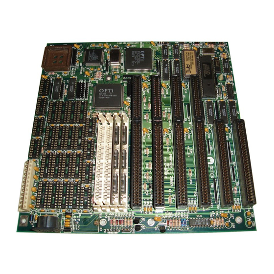
Appendix C System Board Layout _______________________________...
Need help?
Do you have a question about the Panther II and is the answer not in the manual?
Questions and answers