Table of Contents
Advertisement
Quick Links
Advertisement
Table of Contents

Related Manuals for eschmann T20 Series


Summary of Contents for eschmann T20 Series
- Page 1 Series OPERATION TABLES 113158 T-IM114b...
- Page 2 Serial Number. For further information visit www.eschmann.co.uk All correspondence relating to the after sales service of Eschmann Equipment to be addressed to : UK Customers Eschmann Equipment, Peter Road, Lancing, West Sussex BN15 8TJ, England.
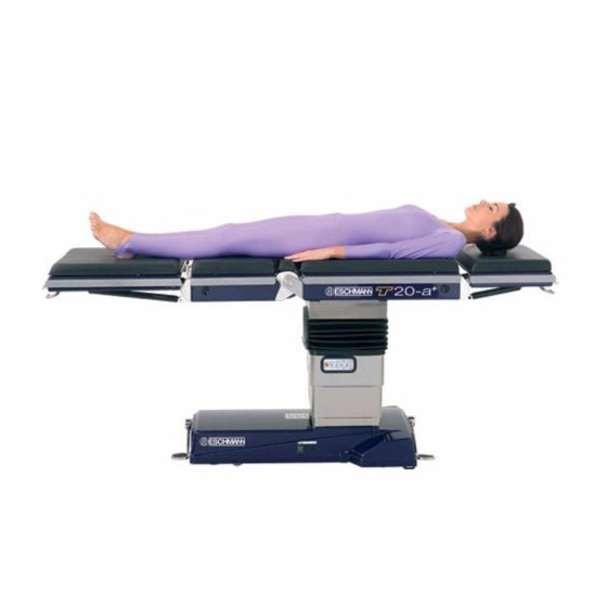
- Page 3 Series OPERATION TABLE The T20 Series of operation table T20-a The T20-a table is a powered operating table suitable for a full range of general and specialist surgical procedures. This operating table has an X-ray translucent traversing tabletop with a built-in X-ray cassette tunnel and is capable of supporting a maximum patient weight of 300kg (mobile 135kg).
-
Page 4: Table Of Contents
CONTENTS 5.3.4 Using the standby control panel ..... 31 1.0 PRELIMINARY INFORMATION ....6 5.3.5 Fuse replacement ........31 General 6 About this manual .......... 6 6.0 PATIENT POSITIONING ..... 32 Table description ........... 7 General ............. 32 2.0 TABLE PARTS AND SYMBOLS ..... 8 Treatment of the obese patient .... - Page 5 Series OPERATION TABLE FIGURES AND APPENDICES Fig. 2.1 Identification of the main parts of the T20 Series table top............10 Fig. 2.2 Identification of the main parts of the T20-a and T20-s table base and column....11 Fig. 2.3 Identification of the main parts of the T20-m table base and column........12 Fig.
-
Page 6: Preliminary Information
Fig. 2.1). This is also the patient’s ‘left’ trained in the use of the T20 Series powered operating and ‘right’ when lying on the tabletop in a supine tables, during surgical operations and procedures in position, with their head on the head section and accordance with these instructions. - Page 7 The tabletop can be adjusted into the following sections 5.1 and 5.2 respectively). patient positions: 1.3.4 The T20 Series of table are easy to operate, ♦ Supine with C-arm access to patient from nipple theatre staff can quickly learn how to use them correctly region to feet and safely.
-
Page 8: Part Identification
To enable an easy reference to all the symbols and graphics to which it is applied (e.g. head section, under used on the T20 Series of tables (and within these the mattress) should not be used as a seat. ‘Instructions for use’) the following grouped sections show This symbol indicates the ‘Safe working load’... -
Page 9: Handset Button Symbols
Series OPERATION TABLE 2.2.2 Handset button symbols 2.2.3 Handset graphics The following symbols are shown on the handset buttons This graphic is shown on the corded to indicate their function. Use of the handset is fully detailed handset to indicate the battery charge in section 5.3.3 of this manual. - Page 10 Head section release bar Head section gas spring Leg section release bar * Clip on handset must match side rail type, see accessory section 4.8 Fig. 2.1 Identification of the main parts of the T20 Series table top. P10/62 T-IM114b...
- Page 11 Mains ‘on’ and Main Battery charging state LED. Red, Amber or Green. Mains ‘on’ and Standby Battery charging state LED. Red, Amber or Green. Connection socket for mains (ONLY use Eschmann mains cord supplied) Castor foot pedal Wheel foot pedal...
- Page 12 Note: Castor covers (spats) are supplied as an optional item (see section 1.3.12) The following items on the column are identical to the T20-a table: Connection socket for Eschmann handset (ONLY) - see item 3, Fig. 2.2 Connection socket for Eschmann footswitch (ONLY) - see item 6, Fig. 2.2 Standby control panel - see item 12, Fig.
-
Page 13: Installation
Series OPERATION TABLE 3.1.6 The T20 Series of table require a mains electrical 3.0 INSTALLATION supply corresponding to the voltage shown on the Serial Number Plate located on the table base. Only use the 3.1 General Eschmann mains supply cord provided with the table. -
Page 14: Lifting The Operation Table
The following sections are provided for the user record those people trained in the safe use of this operation to note prior to using a T20 Series of operation table. table. It is suggested that this is used to ensure that ALL personnel using this table, are aware of all the warnings 3.3.2... -
Page 15: Safety Notes & Cautions
WARNINGS responsibility of the operating surgeon to make sure that the positions, and the positioning The T20 Series of table have been designed to procedures are appropriate for the operation minimise the possibility of accidental to be performed, and the safety of the patient. -
Page 16: Do's And Don'ts
Do not put sharp objects on, or against, mattresses, Attention to the following points will prolong the life and pads, or the radiographic tabletop. efficiency of the T20 Series of table and will help to avoid ♦ Do not place any objects on the base covers the risk of accidents, or damage. -
Page 17: Manual Handling
4.5.1 During adjustment or changing the configuration of the T20 series of operation tables, there are occasions when the user should be aware of the safe practises to be employed during manual handling or adjustment of parts of the table. -
Page 18: Operating The Table
manual operations achieved by using one or both of the 5.0 OPERATING THE TABLE foot pedals on the table base. This section has been split into sections as follows: The table should always be left in the ‘braked’ orientation with both pedals in their raised positions. Do not leave the Moving/operating the table base. -
Page 19: Castor' Orientation (From 'Braked')
Series OPERATION TABLE 5.1.1.4 ‘Braked’ orientation When placed into the ‘castor’ orientation the table base is supported on four castors, two at each end of the table. To place the table into the ‘braked’ orientation move the pedals This orientation enables the table to be moved in any (items 10 and 11, Fig. -
Page 20: T20-M Table Base
BRAKED TABLE WILL NOT MOVE WHEEL PUSH IN A STRAIGHT LINE CASTOR PUSH IN ANY DIRECTION Fig. 5.3 T20-a and T20-s foot pedal quick reference guide Do not operate the pedal from the end of the table when a 5.1.2 T20-m table base long table section (e.g. - Page 21 Series OPERATION TABLE Illustration of the table’s base ‘quick reference guide’ label. Note the booklet symbol that indicates reference to these instructions should be observed. 113136-01 Detail of the required short trunk end castor postion, which should be obtained, before lifting the foot pedal into its top position to place the table base into the 'wheel' mode.
-
Page 22: Wheel' Mode
5.1.2.4 ‘Wheel’ mode Fourth and finally, continue to push the table in a straight line, the short trunk end castors will lock automatically in line with the table base. This enables the table to be moved WARNING easily down a corridor, being steered from the long trunk Do not push the table in the ‘wheel’... -
Page 23: Using The Removable Sections
Also to minimise weight for all users remove mattresses before fitting or removing a section. Users of earlier Eschmann tables (e.g. MR and RX Series) should note that T20 guide pins are shorter and disengage earlier. -
Page 24: Removing A Tabletop Section
Gently insert the section pins into the tabletop and slide the section into the tabletop evenly until the locking catches engage with an audible click. The section will slide in easily if the weight of the section is gently supported with both hands. Take care not to trap anything (especially fingers) between the section and the tabletop. -
Page 25: Changing Sections During A Procedure
Only use Eschmann mattresses and ensure they are free of cuts and tears, replacing as CAUTION required. Do not use without a mattress fitted Continued use of the table batteries when to the table. -
Page 26: Battery Charging
Main battery level indicator: 5.3.1.2 Battery charging Green LED ‘on’ = Battery level satisfactory. To recharge the table batteries (normal and standby) connect the mains cord supplied with the table (do not Amber LED ‘on’ = Low battery. An indication that use any other mains cord) into the mains inlet (item 18, the remaining battery charge is only adequate for Fig. -
Page 27: Powered Motions
Series OPERATION TABLE 5.3.2 Powered motions Powered tabletop motions are, Trendelenburg, height, tilt, brake, traverse, flexion and return to level. Each motion in either direction is controlled by pressing and holding the WARNING appropriate handset, footswitch or standby control panel Always ensure that the patient is secure or button. -
Page 28: Tabletop Motions
5.3.2.2 Tabletop motions 5.3.3 Using the handset WARNING 5.3.3.1 General Ensure you have read and understood the WARNING safety warnings listed in section 4.1 and 5.3.2 Do not plug two handsets into the table at the before using any of the powered motions. same time. -
Page 29: Handset Button Functions
Series OPERATION TABLE 5.3.3.2 Handset button functions B11 Extension - Press to move table into Extension. Handset buttons have their function indicated by graphics printed on the handset, see Fig. 5.12. B12 Flexion - Press to move table into To activate the required tabletop motion press and hold Flexion. - Page 30 T20-a / T20-s Serial label (end of table base) T20-m Serial label (on trunk section) T20A1JI090 REF T20-1-3-1101 2005-08 Fig. 5.12 Handset button functions and serial labels (labels are examples only and text on actual table will be different to that shown above) P30/62 T-IM114b...
-
Page 31: Using The Standby Control Panel
Series OPERATION TABLE 5.3.4 Using the standby control panel Trendelenburg - Press and hold this button, then press required direction button to rotate the tabletop in the Trendelenburg (button OB6, Fig. 5.13) or reverse WARNING Trendelenburg direction (button OB7, Fig. 5.13) The standby control panel MUST be used with Height - Press and hold this button, then press extreme care for Trendelenburg movements. -
Page 32: Patient Positioning
6.2. 6.1 General The Figures in section 6.4 provide details of various patient positions that can be arranged with the T20 Series of table. Note that these illustrations are examples only and care WARNING should be taken to ensure patient safety and table stability. - Page 33 Series OPERATION TABLE Patient positioning for maximum ‘C’ arm imaging of the required area. Additionally there is an X-ray cassette tunnel, accessible from either end. Lower torso imaging Patient in normal orientation with table head and leg sections in the normal position.
- Page 34 When moving the table with a patient, ensure their centre of gravity lies within the bold vertical lines in all cases. Fig. 6.3 Maximum patient weight v table position graphs (head and leg section in normal positions). P34/62 T-IM114b...
- Page 35 Series OPERATION TABLE When moving the table with a patient, ensure their centre of gravity lies within the bold vertical lines in all cases. Fig. 6.4 Maximum patient weight v table position graphs (head and leg section reversed). T-IM114b P35/62...
- Page 36 Fig. 6.5 Patient in various ‘Supine’ positions (Note: For maximum patient weights see Fig. 6.3 and 6.4) P36/62 T-IM114b...
- Page 37 Series OPERATION TABLE Fig. 6.6 Patient in various ‘Prone’ positions (Note: For maximum patient weights see Fig. 6.3 and 6.4) T-IM114b P37/62...
- Page 38 Note warnings in section 2.1 regarding patient support. Fig. 6.7 Patient in various ‘Lawn chair’ & ‘Trendelenburg’ positions (Note: For maximum patient weights see Fig. 6.3 and 6.4) P38/62 T-IM114b...
- Page 39 Series OPERATION TABLE Fig. 6.8 Patient in various ‘Chair’ positions (Note: For maximum patient weights see Fig. 6.3 and 6.4), but note that with the table and patient positioned as above these are basically stable positions) T-IM114b P39/62...
- Page 40 Note: Maximum patient weight for these two positions is 85kg. Note: Iliac crest support may be useful to reduce knee damage for all three positions. Fig. 6.9 Patient in various ‘Proctology’ positions (Note: For maximum patient weights see above and Fig. 6.3 and 6.4), note that table stability in the top two graphics is the lowest and can only be used for the lighter patient) P40/62 T-IM114b...
- Page 41 Series OPERATION TABLE Fig. 6.10 Patient in ‘Lithotomy’, ‘Prone Laminectomy’ and ‘Lateral Nephrectomy’ (Note: For maximum patient weights see Fig. 6.3 and 6.4) T-IM114b P41/62...
-
Page 42: Accessories
TA-0303004 Accessory attachment bar and the patient’s anatomy and a range of support and Gel pads, suitable for use on the T20 Series of tables. TA-0401013 Accessory trolley Direct Placement Leg Holders (DPLH) which can be... - Page 43 Series OPERATION TABLE The following accessories can be used with the T20 Series of tables. Their use is self explanatory but always ensure all clamps are fully tightened before using to support the applicable part of the patient’s weight. Some of these require additional clamps to secure them to the table this is indicated in the following list.
-
Page 44: After Use, Cleaning & Care
If you have any particular cleaning problems, contact the disinfected in accordance with local procedures which take Eschmann Equipment After Sales Service Department at into account the guidelines provided in section 8.2 and 8.3 the address given inside the front cover of this Manual. -
Page 45: Disinfection
Remove all mattresses and check them for any cuts, The following disinfection procedure is used by Eschmann scuffs or other damage and replace as required. Equipment, and its use is recommended if no other local Check that the table covers are not cracked, approved procedures are available. -
Page 46: Storing The Operation Table (Long Term)
1.1.6, 3.3.9 and 8.4. standards but as with all other electro-mechanical products, the Eschmann T20 Series of tables is subject to ageing 8.6.2 Fault diagnosis and wear, and even though the product may have... - Page 47 Series OPERATION TABLE STORAGE MAINTENANCE RECORD (for Table Serial No : ..........) Date of Date of Signature Comment Battery Charge Inspection T-IM114b P47/62...
- Page 48 TABLE 1 - FAULT DIAGNOSIS FAULT POSSIBLE CAUSE REMEDY Table will not move in Table not switched ‘on’. Switch table ‘on’, switch 5, Fig. 2.2. response to handset or footswitch. Main batteries critically low, Recharge batteries see section 5.3.1.2 see 5.3.1.1 and Fig. 5.9. OR, in an emergency only control the table using the standby control panel as detailed in section 5.3.4,...
- Page 49 Series OPERATION TABLE TABLE 1 - FAULT DIAGNOSIS (continued) FAULT POSSIBLE CAUSE REMEDY Table will not move Table base in ‘braked’ position. Place table into the ‘castor’ or ‘wheel’ when pushed. orientation as detailed in section 5.1. Foreign object trapped under Check for foreign object and remove a wheel or castor.
-
Page 50: Technical Data
(with head and leg sections fitted) and electrically conductive or antistatic floor and include the standard 50mm mattress and side rail if with mattresses supplied by Eschmann applicable (see Fig. 9.1 for illustration, the number in Equipment. brackets after the item details which part):... - Page 51 Series OPERATION TABLE 725mm* 610mm* T20-a and T20-s T20-m These are maximum movements for each aspect, they may not be available in certain combinations (e.g. maximum tilt and maximum Trendelenburg). Movements that could cause damage cannot be catered for (e.g. position of the leg section).
-
Page 52: Fuses
Mains input fuses (item 13, Fig. 2.2 or item 5, Fig. 2.3) 2 x T4A (5 x 20mm) 250V The T20 Series of operation table have been designed to minimise the possibility of accidental electrosurgery burns Battery fuses (item 2, Fig. 2.2). Note: On the T20-m and can be used in conjunction with electrosurgical these fuses are fitted internally. -
Page 53: Audible
9.11.2 Interference from other equipment All the other accessories listed in section 7.0 are designed for use with the Eschmann T20 Series of tables and have The Eschmann T20 Series of tables have been designed no EMC implications. to ensure that when using them in close proximity with ‘other correctly designed’... - Page 54 Guidance and manufacturer’s declaration - electromagnetic emissions The T20 Series of operation table are intended for use in the electromagnetic environment specified below. The customer or the user of these operation tables should assure that they are used in such an environment...
- Page 55 Guidance and manufacturer’s declaration - electromagnetic immunity The T20 Series of operation table are intended for use in the electromagnetic environment specified below. The customer or the user of these operation tables should assure that it is used in such an environment...
- Page 56 To assess the electromagnetic environment due to fixed RF transmitters, an electromagnetic site survey should be considered. If the measured field strength in the location in which the T20 Series of operation table are used exceeds the applicable RF compliance level above, the T20 table should be observed to verify normal operation.
- Page 57 T20 Series of operation table The T20 Series of operation table are intended for use in an electromagnetic environment in which radiated RF disturbances are controlled. The customer or the user of the T20 operation table can help prevent electromagnetic...
- Page 58 APPENDIX 1 TRAINING LOG FOR THE ESCHMANN T20 SERIES OPERATION TABLE NAME POSITION DATE INSTRUCTOR AUTHORIZED BY REVIEW DATE Ensure that ALL the personnel listed above have been fully trained in the safe use of this T20 Operation table. This should include a thorough understanding of all the safety notes and cautions contained within this ‘Instructions for use’...
- Page 59 Series OPERATION TABLE APPENDIX 2 DECONTAMINATION CERTIFICATE Make and description of equipment/item: Catalogue number (REF)*: Serial Number (SN)*: This is to certify that the above equipment/item has been decontaminated in accordance with the attached procedure and that this certificate has been issued by the authorized person detailed below.
- Page 60 APPENDIX 3 BATTERY MANAGEMENT SHEET FOR THE ESCHMANN T20 OPERATION TABLE CAUTION Continued use of the table batteries in the ‘critically low’ state can damage the batteries. Batteries within the table base are mains rechargeable, to maintain peak battery performance the table batteries should be placed ‘on charge’...
- Page 61 During configuration or adjustment of the T20 series reasonably practicable. It states that it is the Duty of of table there are occasions where the user should be...
- Page 62 position and type of grip depends on the circumstances and individual preference; but it must be secure. A hook grip is less tiring than keeping the fingers straight. If you need to vary the grip as the lift progresses, do it as smoothly as possible. PERFORM - Keep close to the load.
- Page 64 Eschmann Equipment, Peter Road, Lancing, West Sussex, BN15 8TJ, England. Tel: +44 (0) 1903 753322. Fax: +44 (0) 1903 875789. www.eschmann.co.uk...
Need help?
Do you have a question about the T20 Series and is the answer not in the manual?
Questions and answers