Table of Contents
Advertisement
Advertisement
Table of Contents

Related Manuals for eschmann T20-a


Summary of Contents for eschmann T20-a
- Page 1 T20-a OPERATION TABLE 111707 T-SM47j...
- Page 2 The Serial Number plate is located here For further information visit www.eschmann.co.uk All correspondence relating to the after sales service of Eschmann Equipment to be addressed to : UK Customers Eschmann Equipment, Peter Road, Lancing, West Sussex BN15 8TJ, England.
-
Page 3: Table Of Contents
T20-a OPERATION TABLE 6.2.4 Telescopic covers ....23 CONTENTS 6.2.4.1 Removal of telescopic covers ..23 6.2.4.2... - Page 4 Application software guide ..... 50 Appendix 3 T20-a Table schematics ..... . . 51 Appendix 4 Electrical safety checks .
-
Page 5: Preliminary Information
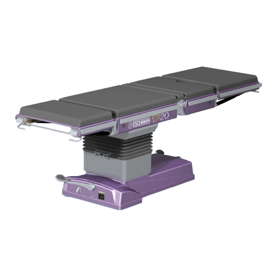
This Service Manual should be referred to for details Fig. 1.0 identifies the main parts of the T20-a of the T20-a Powered Operation Table, Serial Number (SN) operation table. T2AA3A0000 or above: REF T20-223-2301* &... -
Page 6: Identification Of Main Parts
NOTE: The table illustrated has external pedal locking catches. Some tables have internal locking catches, see section 6.2 and 6.3 for details. Fig. 1.0 Identification of main parts P6/54 T-SM47j... - Page 7 14 Pedestal 15 Castor foot pedal 16 Leg section release bar 17 Mains fuses 18 Connection socket for mains (ONLY use Eschmann mains cord, Part No. 391177) 19 Main battery charging state LED: Mains ‘on’, batteries in ‘bulk’ charge Amber Mains ‘on’, batteries in ‘top-up’...
-
Page 8: Technical Data
Dimensions electrically conductive or antistatic floor and The following are the nominal major dimensions of the with mattresses supplied by Eschmann standard table (with head and leg sections fitted) and Equipment. include the 50mm mattress and side rails if applicable (see Fig. -
Page 9: Classification And Symbology
(see note below). Each motor drive has When the T20-a is used in conjunction with other infrared its own duty cycle and this is dependent on loading and controlled devices, their controllers should be checked to table position as detailed below. -
Page 10: Major Dimensions And Movements
These are maximum movements for each aspect, they may not be available in certain combinations (e.g. maximum tilt and maximum Trendelenburg). Movements that could cause damage cannot be catered for (e.g. position of the leg section). Fig. 2.1 Major dimensions and movements P10/54 T-SM47j... -
Page 11: Maximum Patient Weights
T20-a OPERATION TABLE Fig. 2.2 Maximum patient weight v table position graphs T-SM47j P11/54... -
Page 12: Maximum Patient Weights
Fig. 2.3 Maximum patient weight v table position graphs P12/54 T-SM47j... -
Page 13: Technical Description
3.2.1 Overview 3.2.1.3 The ‘4 actuator PCA’ The control electronics for the T20-a is distributed between two PCA’s (the ‘4 actuator PCA’ and the ‘3 actuator PCA’). The ‘4 actuator PCA’ is responsible for movement of four These two PCA’s contain three distinct microprocessor actuators on or within the table’s column. -
Page 14: Handset Overview
RS232. This output is fed to an RS232 line driver. The corded handset’s power is supplied directly from the T20-a, 5V power supply. The handset contains a DC-DC converter to supply 3.3V for the keyboard decoder. There are indicator LED’s to show the charge status of the table batteries (main... -
Page 15: Schematic Diagrams
T20-a OPERATION TABLE PROCESSOR PROCESSOR COMMUNICATIONS CONTROL FET DRIVERS OVER INTERFACE CURRENT MANAGER POSITIONAL MOTOR FEEDBACK CONNECTOR 64 WAY CONTROL FROM HOST MICRO Basic control and feedback - all actuator drivers Processor PCA AXIS TILT Keyboard Battery AXIS TREND AXIS HEIGHT 1... -
Page 16: Safety Warnings
working procedures are employed for an activity that entails 4.0 SAFETY WARNINGS working with mains voltage, such as: Reduce the amount of live work to the minimum ‘Service position’ possible. Use common sense and stop working if When the four M10 screws (each side) that secure the approached, distractions can kill. -
Page 17: Maintenance
T20-a OPERATION TABLE Remove covers and check battery fuses (see MAINTENANCE section 5.3.1 and 6.6.26). Also look to see if the PCA indicator lights are flashing ‘on’ for 1 second Power supply assembly and ‘off’ for 1 second. If they are ‘off’ or flashing faster, this indicates an electronics fault see 5.2.3. -
Page 18: Service Schedule And Safety Check
Service schedule and safety check This should be performed every 6 months to ensure the Prior to changing a motor check it has failed and that continued safe operation of the table. the fault is not in the control electronics (6.6.6 - 6.6.9). In the sections below where the word ‘check’... - Page 19 Leave table clean and in a fully functioning condition with batteries on charge and table switched off. Service / Table details Service Engineer Engineers Name Contact Tel. No..........(Eschmann / Hospital*) ..............Person responsible for table Name ............Position ..........Dept..........Hospital ........... Health Authority ........Tel.No........... Table details Table SN ..........
-
Page 20: Part Removal/Adjustment/ Replacement
6.1.3 All replacement parts must be supplied by 6.2.2 Base covers. Eschmann and note that this also includes all the nuts, screws, roll pins, pivot pins etc. that are specified in the 6.2.3 Access to column. -
Page 21: Replacing Base Covers
T20-a OPERATION TABLE Raise the telescopic covers sufficiently to clear the Raise the telescopic covers to gain access to the base covers and slide the base covers away from lower part of the column. the pedestal column taking care to release the cable... - Page 22 Bellows rivet removal/replacement detail To remove rivets : Pull up plunger head (see B), do not damage rivet head. Pull rivet out of cover (see A). To replace rivets : Align holes in cover sections (see A). Place rivet in hole so that shoulder of rivet shaft is flush with outer cover face (see B).
-
Page 23: Top Of Column Access
T20-a OPERATION TABLE Test that the bellows work correctly by moving table vii Remove the four screws (two per join) holding the through several complete sequences of extreme tilt top telescopic section together and remove the and Trendelenburg (use handset not standby panel). -
Page 24: Replacing The Bellows
Note: The trunk sections may become unstable 6.3.2 Batteries when the M10 screws are removed and extreme IMPORTANT NOTE: care should be taken. Ensure trunks sections are See section 6.6.26 (battery management system supported during removal of these screws. reconditioning) before changing the batteries. Remove the two top location angles (item 15 of Fig. -
Page 25: Front Wheels
T20-a OPERATION TABLE Compress or extend the damper length manually to Use threadlock (part number 670650) on all enable the damper angle bracket to be secured back threads and tighten castor screws to 4Nm. Do onto the base plate using threadlock (part number not overtighten as this can compromise the 670650) on the screw threads. - Page 26 Torque settings M10 x 40mm screws securing item 1 to item 2 = 40Nm. Castor screws = 4Nm (Note: Item 28 no longer fitted) Fig. 6.2a Table base general arrangement (external pedal catch) P26/54 T-SM47j...
- Page 27 T20-a OPERATION TABLE Note: During maintenance of the front pedal or castor Torque settings plate assembly it may be necessary to use shims M10 x 40mm screws securing (item 26). If pedal can be pressed past the locking item 1 to item 2 = 40Nm.
- Page 28 Note: During maintenance of the front pedal or castor Torque settings plate assembly it may be necessary to use shims M10 x 40mm screws securing (item 26). If pedal can be pressed past the locking item 1 to item 2 = 40Nm. point too easily then add a shim.
-
Page 29: Castor Pillar Bushes
T20-a OPERATION TABLE 6.3.7 Castor pillar bushes 6.3.10 Pedal catch block To replace the castor pillar bushes if worn, refer to Fig. 6.2a To replace or adjust the pedal catch block (not fitted to or 6.2b as applicable and proceed as follows: tables with internal catch) if worn or damaged, place the table on a flat floor surface, refer to Fig. -
Page 30: Trendelenburg Actuator
6.4 TABLE COLUMN COMPONENTS 6.4.4 Telescopic column assembly 6.4.1 The following parts on the table column may need WARNING replacement in the event of wear, damage, or malfunction Removal and replacement of the telescopic (see notes below in each section). The procedures for these column assembly entails lifting the trunk are detailed in the sections that follow: sections, the complete wrapround assembly and... - Page 31 T20-a OPERATION TABLE Fig. 6.3 Table column general arrangement T-SM47j P31/54...
-
Page 32: Tilt & Trendelenburg Motor
Reassemble table (see note below) by reversing the Remove the connector assembly block (two screws) above noting use of grease and threadlock in the and release the tilt potentiometer. sections referred to and the warning at the top of Remove two screws at one junction of tilt frame end this section. -
Page 33: Head And Leg Section
(or return 6.5.1.5 Gas spring release handle it to Eschmann Equipment). To release the gas 6.5.1.6 X-ray translucent top (nitrogen and a small amount of hydraulic oil) locate the gas spring positively onto the bed of a drilling See Fig. -
Page 34: General Arrangement, Head & Leg Section
Torque settings Guide pin screw = 8Nm Gas spring shoulder screw = 10 Nm Sidebar screw = 15Nm Fig. 6.4 General arrangement of head and leg section. (Note: Leg section illustrated) P34/54 T-SM47j... -
Page 35: Gas Spring Release Handle
T20-a OPERATION TABLE 6.5.1.4 Gas spring release head / pivot pin 6.5.2.6 Top covers 6.5.2.7 Push button components If the piston end of a gas spring shows sign of excess wear or play at its pivot, remove the pivot pin and release 6.5.2.8... -
Page 36: Traverse Drive Belt
6.5.2.2 Traverse drive belt 6.5.2.3 Break motor To replace a traverse drive belt proceed as follows, noting To replace a break motor proceed as follows noting that comments for later tables: either of the two motors could have failed and both need to be checked: Place the table into the ‘Service position’... - Page 37 T20-a OPERATION TABLE Torque settings Lead screws M10 set screw = 20Nm Actuator arms M8 csk. screw = 14 Nm Sidebar screw = 21Nm Black top M6 csk. screw = 6 Nm All M8 button head screws = 10Nm All M3 Torx cover screws = 0.5Nm Fig.
- Page 38 Torque settings Lead screws M10 set screw = 20Nm Note: On later tables ensure that Actuator arms M8 csk. screw = 14 Nm the grommet strip is in place in Sidebar screw = 21Nm the cable and conduit slot of Black top M6 csk.
-
Page 39: Side Rails
T20-a OPERATION TABLE vii Continue to reassemble the table by reversing the as required during the procedure. On the short trunk it will above (use threadlock part number 670650 on screw be necessary to remove the ‘P’ clip on the break gearbox threads and note any applicable torque values loom and the bottom cover (item 3 and 11 of Fig. - Page 40 Torque settings M10 screw (fixing to column) = 48Nm M6 skt. hd. fixing screw = 9 Nm Fig. 6.7 Table traverse general arrangement P40/54 T-SM47j...
-
Page 41: Drive Belt Guide Bearing
T20-a OPERATION TABLE 6.5.2.9 Drive belt guide needle bearing 6.6 ELECTRICAL COMPONENTS To replace a traverse drive belt guide needle bearing (item WARNING 24 of Fig. 6.7) proceed as follows: Ensure correct procedures are used if mains Remove the motor assembly as detailed in section voltages are exposed. -
Page 42: Three Actuator Pca
6.6.2 Three actuator PCA Remove all connections to the four actuator PCA and remove it from the column (remove the four M4 To replace a three actuator PCA (item 18 of Fig. 6.7) screws and take care not to loose the four small proceed as follows: spacers). -
Page 43: Power Supply Assembly
T20-a OPERATION TABLE 6.6.5 Power supply assembly 6.6.10 Break potentiometer loom 6.6.5.1 The power supply assembly, (item 6 of Fig. 6.8) 6.6.10.1 To replace a break potentiometer loom (see note is replaced as a complete unit. in 6.6.1) remove both the cover over the potentiometer and the short trunk bottom cover (item 3 or 11 of Fig. -
Page 44: Handset Button Functions And Serial Labels
Fig. 6.9 Handset button functions and serial labels Note: Labels shown above are examples, see the applied serial label for the actual data. OLD INFRARED HANDSET NEW INFRARED HANDSET Fig. 6.10 Old and new infrared Handset buttons P44/54 T-SM47j... -
Page 45: Traverse Motor Loom & M'switches
The traverse motor loom and microswitches are within the Remove the trunk sections from the table as crossbeam, see Fig. 6.7. (Note that all T20-a tables have detailed in section 6.2.5 for bellows replacement the later switch arrangement). Change the traverse motor... -
Page 46: Break Gearbox Loom
Remove the cable ties at both ends of the energy 6.6.20 Fuses chain to gain access to the retaining screws securing 6.6.20.1 All the table fuses are detailed in the Technical the energy chain, remove the screws and take off Data Section 2.5.5. -
Page 47: Handset Service
T20-a OPERATION TABLE 6.6.23 Handset service 6.7 FUNCTION TESTS 6.6.23.1 The Handsets do not contain serviceable Before and after any maintenance procedure (part parts but the infrared handset batteries and the spring clips replacement, adjustment, calibration etc.) the table should on either unit can be replaced. -
Page 48: Base Pedals
6.7.8 Base pedals 6.8 ACCESSORIES Most accessories are basic in nature and part replacement Operate each base pedal to ensure it functions correctly, is not usually required. Servicing is covered for similar items that motion is correctly damped by the spring damper and in the preceding sections (e.g. -
Page 49: Torque Conversions
T20-a OPERATION TABLE APPENDIX 1 - TORQUE CONVERSIONS In the text of this document torque values are all detailed in Nm. If the torque tools being used are imperial use the chart below to convert the values to either ‘lb in’ or ‘lb ft’ as required. -
Page 50: Application Software Guide
APPENDIX 2 - APPLICATION SOFTWARE GUIDE When some parts are replaced it will be necessary to reprogram, reconfigure or recalibrate the table PCAs. The following list provides guidance on which parts and what actions need to be taken, when these parts are changed. After reassembling the table but before refitting covers (especially the short trunk black top in some cases) the table should be connected to a PC (boards and protractor if required) to enable the following procedures to be followed. -
Page 51: A1 T20-A Schematic Diagram - Base Section
T20-a OPERATION TABLE APPENDIX 3 - SCHEMATIC DIAGRAMS Fig. A1 T20-a Schematic diagram - Trunk Section T-SM47j P51/54... -
Page 52: A2 T20-A Schematic Diagram - Pedestal Section
Fig. A2 T20-a Schematic diagram - Pedestal Section P52/54 T-SM47j... -
Page 53: A3 T20-A Schematic Diagram - Trunk Section
T20-a OPERATION TABLE Fig. A3 T20-a Schematic diagram - Base Section T-SM47j P53/54... -
Page 54: Electrical Safety Checks
Connect the cords from the DVM (either way round) the current requirements for PAT (Portable Appliance to the two ‘Black’ sockets of Tool 110721. Testing) tests as detailed in the Eschmann Service Schedule No. 2011. With switches 1 and 2 of the Tool ‘off’ and switch 3 ‘on’, the DVM should read, ‘>10µA &... - Page 56 Eschmann Equipment, Peter Road, Lancing, West Sussex, BN15 8TJ, England. Tel: +44 (0) 1903 753322. Fax: +44 (0) 1903 875789. www.eschmann.co.uk...
Need help?
Do you have a question about the T20-a and is the answer not in the manual?
Questions and answers