Table of Contents
Advertisement
Quick Links
Advertisement
Table of Contents

Related Manuals for eschmann RX500


Summary of Contents for eschmann RX500
- Page 1 RX500 O P E R AT I O N TA B L E 698265 T-SM13h...
- Page 2 For further information visit www.eschmann.co.uk All correspondence relating to the after sales service of Eschmann Equipment to be addressed to : UK Customers Eschmann Equipment, Peter Road, Lancing, West Sussex BN15 8TJ, England.
-
Page 3: Table Of Contents
Head, Leg, & Infill-Locking Mech..14 3 RX500 Operation Table: Column/Trunk Detail 12 Long and Short Trunk Sections ..... 14 4 RX500 Operation Table: Base (short trunk end) ..13 Radiographic Tops ......... 14 5 RX500 Operation Table: Base (long trunk end) ..13 Underside of the Table Base .... -
Page 4: Preliminary Information
1. PRELIMINARY INFORMATION This Service Manual should be referred to for details of the RX500 Powered Operation Table, REF 80-600-29 (series) and REF 80-600-61 (series) having Serial Number R5BC8J0000 or above. Related Technical Publications, available on request from Eschmann Equipment :-... -
Page 5: Safety Notes
Type ..... Eschmann RX (Part No. 699408) 3. SAFETY NOTES Attention to the following points will prolong the life and efficiency of the RX500 Powered Operation Table and will help to avoid the risk of accidents, or damage. DO NOT: ♦... -
Page 6: Introduction
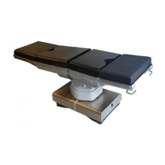
Removable mains lead Hand control or footswitch socket Cover retaining screws Hand control or footswitch socket Top of column covers View on base short trunk end View on base long trunk end Fig. 1 RX500 Powered Operation Table 6/40 T-SM13h... -
Page 7: General
RX500 Powered Operation Table. to the base distribution board, motor on/off control The RX500 Powered Operation Table is a fully and motor direction control. The main control board mobile table with a five section top comprising short is supplied with 24V d.c. -
Page 8: Base Distribution Board
Hand control 4.17 This board receives signals from the main 4.24 The RX500 hand control communicates with control board for the height (extend) solenoid, the the main control board via an RS485 serial height (contract) solenoid, the pump-isolate (forward) communication link. The hand control contains a solenoid and the pump-isolate (reverse) solenoid. -
Page 9: Built-In Battery Charger
RX500 table via hydraulic connectors and an electrical socket behind 4.31 The mains input comes via the mains lead, the door on the table base (short trunk section end). -
Page 10: Description
5. DESCRIPTION For greater detail of the table base ends also refer to Fig. 4 and 5 Fig. 2 RX500 Operation Table : Base details, covers on and off 10/40 T-SM13h... - Page 11 RX500 RX500 RX500 RX500 RX500 OPERATION TABLE 5. DESCRIPTION Key to Figs 2 and 3 27. Base distribution PCB 1. Short trunk assembly 2. Long trunk assembly 28. Castor frame assembly 3. Lateral tilt cylinder 29. Manifold block No 2 4.
- Page 12 5. DESCRIPTION Fig. 3 RX500 Operation Table : Column and trunk section detail 12/40 T-SM13h...
-
Page 13: Rx500 Operation Table: Column/Trunk Detail 12 4 Rx500 Operation Table: Base (Short Trunk End)
Standby power pack connector Base cover microswitch External battery charger socket Fixing for cover retaining screw Fig. 4 RX500 Operation Table Base Detail (Short trunk end) Base cover microswitch Base cover microswitch Mains charging LED Mains connection socket Fixing for cover retaining screw Fig. -
Page 14: Maintenance
For cleaning and storage instructions of the been removed, functions correctly (refer to table refer to the RX500 Powered Operation Table sections 6.48 and 6.49). Apply a smear of light Instructions for Use (Publication No. T-IM28). -
Page 15: Access To Fuses
RX500 RX500 RX500 RX500 RX500 OPERATION TABLE 6. MAINTENANCE Access to Fuses 6.13 The mains fuse is found in the table base on the standby panel (item 4, Fig.4). The other three fuses are fitted on the main control PCB (see Fig. 8) in the base of the table underneath the covers. -
Page 16: Hydraulic System - Schematic Diagram
6. MAINTENANCE Fig. 9 Hydraulic system - Schematic diagram 16/40 T-SM13h... -
Page 17: Hydraulic System - Main Components
RX500 RX500 RX500 RX500 RX500 OPERATION TABLE 6. MAINTENANCE Manifold 1 Hydraulic connections Power unit Feed from reservoir Power unit electrical lead Base distribution board Base control board Manifold 2 Trendelenburg cylinder Tilt cylinder Manifold 4 Manifold 3 For break cylinders see Fig.18 and for height cylinder see Fig.22. -
Page 18: Hydraulic System
• Minimum height and onto castors. Notes: • Maximum extension achievable at the Use only Eschmann RX hydraulic oil, Part minimum height set above. No.699408, which is obtainable from Eschmann • Maximum tilt achievable with table at the Equipment or their accredited agents. -
Page 19: Break Microswitch
RX500 RX500 RX500 RX500 RX500 OPERATION TABLE 6. MAINTENANCE Break Microswitch 6.21 To check and adjust the break microswitch (item 1, Fig. 13) proceed as follows: Ensure the table is on a level floor. On the hand control, press the break (extension) button and move the table top to the maximum break (extension) position. -
Page 20: Tilt Switch
6. MAINTENANCE Tilt Switch REMOVAL AND INSTALLATION 6.22 To adjust the tilt switch (item 4, Fig. 14) General proceed as follows: 6.23 All equipment in the base of the operation Ensure the table is on a level floor. table is accessible after the base covers have been removed (see section 6.24). -
Page 21: Remove Top-Of-Column Covers
RX500 RX500 RX500 RX500 RX500 OPERATION TABLE 6. MAINTENANCE To install the long trunk end base cover proceed Install Top-of-Column Covers as follows referring as required to Fig.1 and 2 : Note: Before replacing covers check that all cables Press two springs at the long trunk end... -
Page 22: Top Of Column Hinge Assembly Detail
6. MAINTENANCE Yoke pivot bolt Spring washer Yoke Sel-Lok pin Tilt opto flag Yoke pivot Tilt opto board Top of column casting Washer Yoke pivot bush Tilt hanger Microswitch plate Microswitch Microswitch adjusting screws Top of column distribution board Hinge plate Height cylinder locking screws Column assy. -
Page 23: Remove Long & Short Trunk Assemblies
RX500 RX500 RX500 RX500 RX500 OPERATION TABLE 6. MAINTENANCE pinched, chaffed or cut by any moving parts and that Remove the ty-wrap straps which secure the the ribbon cable mechanisms are working correctly. hydraulic hoses and the electrical wires to the yoke and move the hydraulic hoses and 6.31... -
Page 24: Break Cylinders
6. MAINTENANCE 1 Short trunk assembly 2 Short trunk pivot pin 3 Hydraulic connection 4 Hydraulic hoses 5 Hydraulic connection 6 Long trunk pivot pin 7 Break cylinder 8 Long trunk assembly 9 Break microswitch Fig. 18 Break cylinders 24/40 T-SM13h... -
Page 25: Lateral Tilt Cylinder
RX500 RX500 RX500 RX500 RX500 OPERATION TABLE 6. MAINTENANCE Tilt cylinder Hydraulic connection Top of column solenoid board Clevis nut Pivot pin grub screw Pivot pin Tilt hanger Microswitch adjusting screws Break microswitch Clevis ‘R’ clip Washer Pivot pin Fig. 19... -
Page 26: Remove Break Cylinder
6. MAINTENANCE Apply Rocol white grease (Part No.110477) to Top up the hydraulic system reservoir as the Yoke pivot bush (item 11, Fig. 16) and install described in section 6.18. into the inner column. xiii Check and adjust the Trendelenburg and break Using at least two people, carefully lift and correctly microswitches, lateral tilt opto and tilt switch as position the long and short trunk assemblies onto... -
Page 27: Remove Lateral Tilt Cylinder
RX500 RX500 RX500 RX500 RX500 OPERATION TABLE 6. MAINTENANCE the pivot pin in the short trunk and the break cylinder out a functional test of the operation table as piston eye-end. Secure the pivot pin to the short described in section 6.16. -
Page 28: Install Trendelenburg Cylinder
6. MAINTENANCE pivot pin (item 4, Fig. 17) and remove the pivot pin Remove the eight screws (item 8, Fig.22) and to disconnect the eye-end of the Trendelenburg washers and remove the two clamp blocks (item cylinder from the long trunk assembly (taking care 3, Fig. -
Page 29: Gas Spring Replacement
RX500 RX500 RX500 RX500 RX500 OPERATION TABLE 6. MAINTENANCE Position the pivot pin on the base of the table Using the cord provided, lift the batteries from and secure it with two clamp blocks. Secure the base. two clamp blocks with eight screws and washers. -
Page 30: Install The Base Feet
6. MAINTENANCE Install the Base Feet Push button replacement and adjustment 6.47 To install the base feet, proceed as follows: 6.48 To replace the push-button catches remove any attached table section, refer to Fig.26 and Install each of the four corner feet as follows: proceed as follows: Fit two new Sel-Lok pins into the foot, ensur- Remove screw (1) to release the push-button. -
Page 31: Fault Diagnosis
(see Index on page 33). For any faults, listed or not, which cannot be resolved, please contact the Eschmann After Sales Service Department; for details see inside front cover. - Page 32 6. MAINTENANCE TABLE 1 - FAULT DIAGNOSIS Fault/Condition Possible Cause Remedy 7 Code 05 is displayed and The applicable table motion Switch the table ‘off’, using an LED is illuminated (see below), has been used for more than the table on/off switch, (Fig.1 the Table stops moving and there 40 seconds (consider whether item 18), and then switch back ‘on’.
- Page 33 Page No. 699501 Base distribution board 699569 Opto board 699497 Top-of-column solenoid board 699755 Pin connections 700303 Tilt opto board 699495 Top-of-column distribution board 699980 Battery charger distribution board 699819 RX500 Main control board 699364 RX500 System diagram T-SM13h 33/40...
-
Page 34: Hand Control Functions
6. MAINTENANCE Patient orientation button and green indicator. Patient orientation button and green indicator. Trendelenburg button (orange). Reverse Trendelenburg button. Break (Extension) button. Break (Flexion) button. Lateral tilt button. Lateral tilt button. Table raising button. Table lowering button. Return to pre-set (auto level) position button. Castor button and yellow indicator. -
Page 35: 28-35Circuit Diagrams
RX500 RX500 RX500 RX500 RX500 OPERATION TABLE 6. MAINTENANCE Fig. 28 Base Distribution Board Fig. 29 Opto Board T-SM13h 35/40... - Page 36 6. MAINTENANCE Fig. 30 Top-Of-Column Solenoid Board Fig. 31 Pin Connections Fig. 32 Tilt opto board 36/40 T-SM13h...
- Page 37 RX500 RX500 RX500 RX500 RX500 OPERATION TABLE 6. MAINTENANCE Fig. 33 Top-Of-Column Distribution Board T-SM13h 37/40...
- Page 38 6. MAINTENANCE Fig. 34 Battery Charger Distribution Board 38/40 T-SM13h...
- Page 39 RX500 RX500 RX500 RX500 RX500 OPERATION TABLE T-SM13h 39/40...
- Page 40 Eschmann Equipment, Peter Road, Lancing, West Sussex, BN15 8TJ, England. Tel: +44 (0) 1903 753322. Fax: +44 (0) 1903 766793. www.eschmann.co.uk...
Need help?
Do you have a question about the RX500 and is the answer not in the manual?
Questions and answers