Table of Contents
Advertisement
Quick Links
Advertisement
Table of Contents

Related Manuals for eschmann TD830


Summary of Contents for eschmann TD830
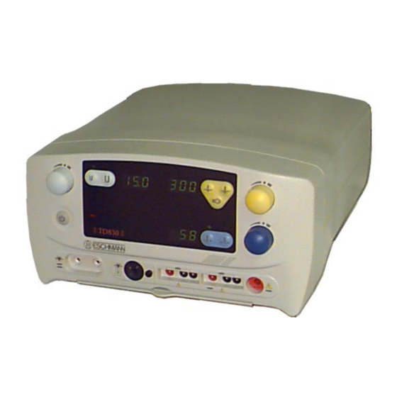
- Page 1 TD830 E LECT RO SURGICAL UNIT 698257 E-IM54f...
- Page 2 (view from rear of unit). For further information visit www.eschmann.co.uk All correspondence relating to the after sales service of Eschmann Equipment to be addressed to : UK Customers Eschmann Equipment, Peter Road, Lancing, West Sussex BN15 8TJ, England.
-
Page 3: Table Of Contents
TD830 ELECTROSURGICAL UNIT CONTENTS 5. OPERATION 1. PRELIMINARY INFORMATION Preliminary information ......4 Routine check ......16 Connection of accessories . -
Page 4: Preliminary Information
These Instructions for Use should be referred to for mains supply. A complete systems check must be carried details of the TD830 Electrosurgical Unit, REF 83-256-01, out before using the Electrosurgery Unit (see Sections 5.10 83-257-02, 83-258-03, 83-259-04, 83-260-05, 83-261-01, to 5.17). -
Page 5: Technical Data General
ELECTROSURGICAL UNIT Output (bipolar) 2. 0 TECHNICAL DATA Peak GENERAL Open Crest Circuit The TD830 Electrosurgical Unit (or Surgical Diathermy Symbol/Function Power factor Voltage Unit) is classified as ‘HF surgical equipment’ Coagulation - ‘HF surgical equipment’ is defined as, “Medical... -
Page 6: Audible Indicators
Pinpoint coag (green) Flammable gases Spray coag (bright green) The TD830 equipment is not suitable for use in the presence of a flammable anaesthetic mixture with air or Bipolar: with Oxygen or Nitrous Oxide. -
Page 7: Duty Cycle
TD830 ELECTROSURGICAL UNIT DUTY CYCLE The symbols adjacent to the mains ‘on/off’ switch The duty cycle rating of 10 seconds ‘on’, 30 seconds ‘off’, (42) indicate the ON and OFF positions respectively. specified on the serial plate as 10s:40s, indicates that the equipment can be used at full output power in any mode for 10 seconds with a 30 seconds rest period. -
Page 8: Alarm Symbols
ALARM SYMBOLS - Indicates the ‘Plate continuity monitor’ alarm has been activated. - Indicates the ‘Plate attachment monitor’ alarm has been activated. - Indicates the ‘Patient earth monitor’ alarm has been activated. - Indicates the ‘Plate voltage monitor’ alarm has been activated. -
Page 9: 3.0 Safety Notes & Alarms
DO NOT: ♦ ♦ Use only Eschmann accessories, in particular active Do not use uninsulated forceps, monopolar or bipolar. and plate electrodes and cables which should ♦ Do not place monitoring electrodes close to the preferably be no more than 3 metres in length. -
Page 10: Alarm Circuits
If such an earth path is ♦ Contact the hospital electronics engineer or Eschmann present, the alarm will operate until the path has been After Sales Service Department if the equipment fails removed and the unit reset by switching ‘off’... -
Page 11: 4.0 Introduction
4.11 The equipment is designed to be used with the output and can be considered as USER 3. Eschmann range of active, plate and bipolar cables. The front panel is colour coded, PALE BLUE for bipolar, OPERATING MODES / DISPLAY OPTION YELLOW for monopolar cut, blend and specialist cut, and BLUE for monopolar coag. -
Page 12: Electrosurgical Techniques
♦ Do not apply the plate electrode adjacent to ECG ELECTROSURGICAL TECHNIQUES electrodes and cables, or to an area where fluids could pool. General ♦ With babies and small children the plate electrode 4.14 When using electrosurgery, it must always be should always be applied to the trunk section of the remembered that its purpose is to cut, destroy or modify body to give maximum contact with the skin. -
Page 13: Active Cables
4.34 If, during a surgical procedure, the output Active Cables appears to drop or the electrosurgical performance 4.25 Only active cables supplied by Eschmann should decreases, stop and check the plate electrode for be used. This is of particular importance, as cables with... -
Page 14: Flammable Anaesthetics And Spirits
(References ¹ and ²) suggest that an implanted pacemaker affecting the TD830, it is good practise, in common with all should be unaffected, or only revert to fixed-rate operation, electrosurgical units, to keep them as far as is reasonably possible from the surgical site. -
Page 15: Using Two Electrosurgical Units
S-Lead [REF 83-139-41 (Olympus 9mm), or REF 83-139-49 (Pentax 8mm)] connected to the 4.54 This electrosurgical unit has dual monopolar outputs S-Lead socket (29, Fig 12) of the TD830 (first come first served) and simultaneous bipolar output. Electrosurgical unit and the flexible endoscope. -
Page 16: 5.0 Operation
If in doubt, discard suspect component and fingerswitch sockets (25) can cause damage substitute with one of known function, to the TD830 if the output is energized by a continuity and condition. footswitch. ♦ A single active cable with 8 mm plug (footswitch ♦... -
Page 17: Bipolar
(42) will come ‘on’ and the front (Fig. 7). panel displays (indicators and digital) will illuminate. ♦ For foot control, use one of the range of Eschmann 5.12 The unit may be in monopolar standby mode, if it is footswitches together with a non-switching active monopolar displays will not be illuminated and monopolar handle. -
Page 18: Operating Instructions
USER 1 and/or USER 2 selection covered by adhesive. With cut and coag power levels 5.19 The TD830 can be used by two monopolar operators both adjusted to zero (for safety) the PEM alarm USER 1 and USER 2 independently of each other but not should operate when a USER 1 footswitch or simultaneously. -
Page 19: Plate Electrode
♦ The plate electrode is correctly positioned, and is in contact with the patient. 5.32 The Eschmann twin footswitch (Fig. 4) has an angled platform with two light-action switches for cut and coag. ♦ The plate electrode cable is intact, and is plugged into Colour coded bars provide foot location and protection unit plate electrode socket (30). -
Page 20: Monopolar Outputs
especially flexible endoscopes. Most urological WARNINGS endoscopes are suitable for spray coag. If in doubt check Footswitches should be used with care at that the voltage rating of the laparoscopic or endoscopic all times and should always be under control instrument is at least as high as the maximum spray coag open circuit voltage of this electrosurgical unit (see of the surgeon or designated assistant, as... -
Page 21: Bipolar Mode
The pneumatic type has a very light action and is characteristics determine the actual power delivered to the suited to procedures where repetitive actuation is needed. tissue for a given control setting. The TD830 electrosurgical unit has a power curve that rises at the low resistance Note: end, this ensures that adequate power is available for ♦... -
Page 22: Alarms
5.55 The output control settings required for a particular 5.57 If more than one output demand is received at the surgical procedure are also dependent on a number of same time (such as two footswitches or a footswitch and a external factors (type of tissue, speed at which the surgeon fingerswitch button being pressed) the unit will produce works, type of electrode in use, area of forcep tips in... - Page 23 Note: An activated PVM alarm will automatically be reset by releasing a depressed footswitch or fingerswitch. If none of the above remedies stop the alarm activated, or the (!) alarm is activated contact Eschmann Equipment and do not use the unit. E-IM54f P23/37...
-
Page 24: Table 1 - Power Output Selection Guide
Table 1 Power Output Selection Guide (for ‘typical’ power display range) Procedure Mode Condition Setting CAUTION Do not use a higher power setting than is necessary General Normal cut Dry field 70 to 90 Pinpoint coag Dry field 25 to 45 Blend Dry field 45 to 70... -
Page 25: Output Diagrams
TD830 ELECTROSURGICAL UNIT MONOPOLAR CUT DIAGRAMS MONOP OLA R C UT (P OW E R v LOA D ) H a lf o u tp u t co n trol s e ttin g Full ou tpu t con tro l s e ttin g... - Page 26 MONOPOLAR BLEND DIAGRAMS MONOP OLA R B LE ND (P OW ER v LOA D ) H alf ou tp ut co ntrol s etting Fu ll o utpu t co n tro l s e ttin g 1000 1500 2000 Load resistance (ohms) MONOPOLAR BLEND (POWER v CONTROL)
- Page 27 TD830 ELECTROSURGICAL UNIT MONOPOLAR SPECIALIST CUT DIAGRAMS MONOP OLA R S P E C IA LIS T C UT (P OW E R v LOA D ) H a lf ou tp u t co ntro l s e tting...
- Page 28 MONOPOLAR PINPOINT COAG DIAGRAMS MONOP OLA R P INP OINT C OA G (P OW E R v LOA D ) H alf ou tpu t con tro l s e ttin g Fu ll o u tp ut co n tro l s etting 1000 1500 2000...
- Page 29 TD830 ELECTROSURGICAL UNIT MONOPOLAR SPRAY COAG DIAGRAMS M O NO P O LA R S P RA Y C OA G (P OW E R v L O A D ) H a lf o u tp u t co n tro l s e ttin g...
- Page 30 BIPOLAR MACRO DIAGRAMS BIPOLAR MAC RO (POWER v LOAD) Macro - H alf output control s etting Macro - Full output control s etting 1000 Load resistance (ohm s) BIPOLAR MACRO (POWER v CONTROL) BIPOLAR MACRO (VOLTAGE v CONTROL) Load resistance 100 (ohms) Open circuit Output control setting (numerical value up to 10) Output control setting (numerical value up to 10)
- Page 31 TD830 ELECTROSURGICAL UNIT BIPOLAR MICRO DIAGRAMS B IPOLA R MIC RO (P OW ER v LOAD ) Micro - H alf output control s etting Micro - Full output control s etting 1000 Load resistance (ohm s) BIPOLAR MICRO (POWER v CONTROL)
-
Page 32: Cleaning, Disinfection & Care
Data). If repeated blowing of a fuse(s) occurs, either when wiped dry. the unit is switched on or during use, call the Eschmann ♦ Do not use excessive amounts of liquid which could After Sales Service Department (see inside front cover). -
Page 33: 7.0 Accessories
TD830 ELECTROSURGICAL UNIT 7.0 ACCESSORIES The accessories in the list below and illustrated where referenced, are all recommended for use with the TD830 electrosurgical unit. (REF = catalogue number) Description Illustration No. Description Illustration No. Active electrode silicone cables Colposcopy electrodes (LLETZ) cone biopsy... - Page 34 83-122-42 83-122-46 83-207-56 83-122-49 83-140-20 83-122-93 83-109-39 83-109-47 83-581-09 83-581-13 83-141-01 83-581-17 83-141-36 83-581-25 83-141-28 83-141-44 83-109-71 P34/37 E-IM54f...
- Page 35 TD830 ELECTROSURGICAL UNIT 83-582-06 83-583-97 83-585-94 (Disposable) 83-135-12 83-137-17 4 m m 83-138-06 83-138-22 8 m m 83-583-62 83-582-14 83-585-45 (Disposable) 83-582-27 83-588-85 83-582-30 83-582-49 83-588-69 83-585-04 (Disposable) 83-585-11 (Disposable) 83-583-89 83-583-90 83-585-56 (Disposable) 83-582-22 83-583-11 83-585-23 (Disposable) 83-588-77 83-588-80...
- Page 36 83-700-01 83-703-03 83-705-08 83-707-02 83-701-09 83-704-00 83-706-05 83-708-18 83-702-06 83-709-07 83-581-76 83-581-68 P36/37 E-IM54f...
- Page 38 Eschmann Equipment, Peter Road, Lancing, West Sussex, BN15 8TJ, England. Tel: +44 (0) 1903 753322. Fax: +44 (0) 1903 875789. www.eschmann.co.uk...
- Page 39 Power output control, BIPOLAR MICRO BIPOLAR selected, indicator (green LED) Touch button, MICRO BIPOLAR MACRO BIPOLAR selected, indicator (green LED) Touch button, MACRO BIPOLAR BIPOLAR digital power display (green seven segment LEDs) BIPOLAR, power activated indicator (blue LED) MONOPOLAR CUT digital power display (green seven segment LEDs) MONOPOLAR CUT, power activated indicator (yellow LED) MONOPOLAR (normal cut) selected, indicator (green LED) Touch button MONOPOLAR (normal cut)
Need help?
Do you have a question about the TD830 and is the answer not in the manual?
Questions and answers