BRONKHORST FLEXI-FLOW Compact Instruction Manual
Hide thumbs
Also See for FLEXI-FLOW Compact:
- Quick start manual (6 pages) ,
- Instruction manual (46 pages) ,
- Quick start manual (17 pages)
Table of Contents
Advertisement
Quick Links
Advertisement
Table of Contents

Related Manuals for BRONKHORST FLEXI-FLOW Compact


Summary of Contents for BRONKHORST FLEXI-FLOW Compact
- Page 1 Instruction Manual FLEXI-FLOW™ Compact Doc. no.: 9.17.158 rev. A Date: 08-04-2022 ATTENTION Please read this document carefully before installing and operating the product. Not following the guidelines could result in personal injury and/or damage to the equipment.
- Page 2 Disclaimer This document has been reviewed and is believed to be accurate. Bronkhorst High-Tech B.V. does not assume liability for errors, inaccuracies or absence of information. The material in this document merely serves information and illustration purposes;...
- Page 3 Check the outside packaging box for damage incurred during shipment. If the box is damaged, the local carrier must be notified at once regarding his liability. At the same time a report should be submitted to your Bronkhorst representative. Carefully remove the equipment from the box. Verify that the contents of the package was not damaged during shipment.
- Page 4 Bronkhorst® Instruction Manual FLEXI-FLOW™ Compact 9.17.158A...
-
Page 5: Table Of Contents
Bronkhorst® Table of contents General information ......................7 Scope of this document . - Page 6 Bronkhorst® Parameters ......................21 4.2.1...
-
Page 7: General Information
Responsibility for the use of the equipment regarding its intended use, suitability for the intended application, cleaning and compatibility of process media with the applied materials lies solely with the user. Bronkhorst High-Tech B.V. cannot be held liable for any damage and/or injury resulting from unintended, improper or unsafe use. -
Page 8: Product Features
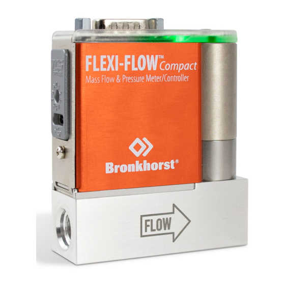
1.4.3 Multi-parameter functionality The FLEXI-FLOW™ Compact works in much the same way as any regular digital Bronkhorst® instrument. Upon delivery, the FLEXI-FLOW™ Compact is configured as a (mass) flow controller. An integrated temperature sensor and 2 pressure sensors provide additional real-time measurement data, allowing the main instrument function to be... -
Page 9: Documentation
At some points it refers to documentation associated with important components or features. These references are listed in the table below. All documents listed here can be found on the FLEXI-FLOW™ product page · (www.bronkhorst.com/flexi-flow or scan the QR code). Type Document name Document no. -
Page 10: Safety Notes
When pressurizing, prevent pressure shocks by gradually bringing the fluid system to the required operating pressure. Bronkhorst does the utmost to ensure that you receive a clean product. This does not, however, relieve the user of the responsibility to ensure that the equipment and the system in which it is incorporated meet the requirements implied by the intended use of the product. -
Page 11: Installation
If you have a question about the product or if you find the product does not meet the specifications as ordered, do not hesitate to contact your Bronkhorst representative (see the first pages of this document). To enable us to help you quickly and effectively, have the serial number ready whenever seeking contact with your Bronkhorst representative about a specific item. -
Page 12: Preventing Pressure Shocks
Route cables as closely as possible alongside metal structures or components. · · Ensure all electrical components are grounded to earth. When in doubt about the shielding of your cabling and/or electrical connections, contact your Bronkhorst representative. Instruction Manual FLEXI-FLOW™ Compact 9.17.158A... -
Page 13: Fieldbus Connection
· · For information about setting up a fieldbus network with Bronkhorst® instruments, consult the according fieldbus manual If you need assistance with setting up a fieldbus network, contactyour Bronkhorst representative for information. · 9.17.158A Instruction Manual FLEXI-FLOW™ Compact... -
Page 14: Operation
First use Bronkhorst does the utmost to ensure that you receive a clean product. This does not, however, relieve the user of the responsibility to ensure that the equipment and the system in which it is incorporated meet the requirements implied by the intended use of the product. -
Page 15: Special Procedures
Bronkhorst® The colors are based on the NAMUR NE 107 standard and are a simplified representation of the instrument's diagnostic · data · After powering up or restarting the instrument, the indication light cycles through all status colors once. ·... -
Page 16: Enabling Bluetooth
Adjusting zero point Zero-stability The zero point of a Bronkhorst® flow meter/controller (the measurement signal that indicates the absence of a flow) is factory adjusted at approximately 20 °C and atmospheric pressure (ambient conditions), with the instrument positioned upright. Under normal circumstances (i.e. at stable process conditions), the zero point will remain stable. However, over time several factors can induce a slight deviation of the measured value from the zero point, causing the instrument to detect a flow when in reality there is none. -
Page 17: Maintenance
To track down problems in the fluid system, depressurize the fluid system and disconnect the suspected unit from the · process line. Dirt or clogging might be quickly detected by visual inspection of disassembled fluid connections. If you suspect leakage, do not disassemble the device for inspection, but contact your Bronkhorst representative for service or repairs. 3.4.1... -
Page 18: Common Issues
Network configuration Invalid baud rate Make sure instrument baud rate matches master/application baud rate Other Reset instrument and/or restart master. If problem persists, contact your Bronkhorst representative No output signal No power supply · Check power supply Check cable connection ·... -
Page 19: Returns
In case of normally open valve: check if valve is in safe state; resolve cause if necessary (see Default valve state Sensor failure Contact your Bronkhorst representative Fluid system leakage Bad connection between parts (e.g. Follow mounting instructions issued by third ferrules, nuts, tubing, piping, party components (e.g. -
Page 20: Disposal (End Of Lifetime)
3.5.2 Disposal (end of lifetime) If you are a customer within the European Union and wish to dispose of Bronkhorst® equipment bearing the symbol of a crossed out waste disposal bin, you can return it in accordance with the removal and return instructions . -
Page 21: Communication Interface
Microsoft Office or custom made software, built with third party development software like LabVIEW or a SCADA platform. The FlowWare tools and associated documentation can be downloaded from the product pages on the Bronkhorst website: www.bronkhorst.com/flexi-flow... -
Page 22: Measurement And Control
Modbus address blocks are two bytes big. Larger data types use up to 8 subsequent address blocks, resulting in a maximum variable length of 16 bytes. Values longer than the maximum length are truncated. For more detailed information about setting up a Modbus network with Bronkhorst® instruments, consult the Modbus manual (see Documentation 4.2.1... -
Page 23: Advanced Measurement And Control
This parameter represents the controller output signal for control valve operation. 4.2.2 Alarms Alarm settings are most easily accessible using FlowSuite, FlowPlot or FlowView or a Bronkhorst® readout and control unit. The built-in alarm functionality can be used to handle different alarm types: system errors and warnings ·... - Page 24 Bronkhorst® Alarm Mode Type Access Range FlowDDE FLOW-BUS Modbus Unsigned char 0…3 97/3 0x0C23/3108 Available modes: Value Description Alarm off Alarm on absolute limits Alarm on limits related to setpoint (response alarm) Alarm at power-up(e.g. after power-down) Alarm Info Type...
-
Page 25: Counter
By parameter Reset Automatically (when alarm conditions no longer apply) 4.2.3 Counter Counter settings are most easily accessible using FlowSuite, FlowPlot or FlowView or a Bronkhorst® readout and control · unit. · When the instrument is powered down, it remembers the state of the counter. If the counter is active when the instrument is powered down, it is activated when powered up and then continues to count from the value at the time of power down. - Page 26 Bronkhorst® Counter Unit supports the following values: Mass Normal volume Standard volume Custom volume (1.01325 bar(a), 0 °C) (1.01325 bar(a), 20 °C) (Capacity Unit Pressure, Capacity Unit Type Temperature) ug, mg, g, kg uln, mln, ln, uls, mls, ls, ul, ml, l,...
-
Page 27: Network Configuration
Bronkhorst® Totalizer Unit Type Access Range FlowDDE FLOW-BUS Modbus Unsigned char[4] 104/18 0xE890…0xE891/59537…59538 parameter Counter Unit This parameter contains the name of the totalizer readout unit. Totalizer Value Type Access Range FlowDDE FLOW-BUS Modbus Float 0… 104/17 0xE888…0xE889/59529…59530 10000000 Current totalizer value in units as selected with parameter Totalizer Unit. -
Page 28: Fluid Set
Bronkhorst® Default settings Network configuration is done ex factory as ordered. The table below shows the supported configurations for the available interface protocols (default settings are printed in bold): Protocol FLOW-BUS Modbus RTU Address 3…125 1…247 Baud Rate 9600 187500... -
Page 29: Advanced Fluid Set Parameters
Bronkhorst® This parameter represents the unit in which the Capacity 0%/100% parameters are expressed. Available units: Mass flow Normal volume flow Standard volume flow Custom volume flow (1.01325 bar(a), 0 °C) (1.01325 bar(a), 20 °C) (Capacity Unit Type Pressure, Capacity Unit Type... -
Page 30: Fluid Mixture Parameters
Bronkhorst® Fluid Temperature Type Access Range FlowDDE FLOW-BUS Modbus Float -250…500 113/16 0xF180…0xF181/61825…61826 Temperature of the selected fluid in °C. Density Type Access Range FlowDDE FLOW-BUS Modbus Float 0…3.4E+38 33/21 0xA1A8…0xA1A9/41385…41386 Density of the selected fluid in kg/m Heat Capacity... -
Page 31: Master/Slave Configuration (Flow-Bus)
Bronkhorst® Mix Component Index Type Access Range FlowDDE FLOW-BUS Modbus Unsigned char 0…4 126/7 0x0FC7/4040 Index of the current component in the mixture (max. 5 components). Mix Component Fraction Type Access Range FlowDDE FLOW-BUS Modbus Float 0…1 126/8 0xFE40…0xFE41/65089…65090 Mix fraction of the current mix component (Mix Component Index). The value range corresponds to 0…100%. The sum of the all mix fractions must be equal to 1. -
Page 32: Digital Input And Output
FLOW-BUS Modbus Unsigned char[20] 113/3 0xF118…0xF11F/ 61721…61728 Instrument serial number for identification. BHT Model Number Type Access Range FlowDDE FLOW-BUS Modbus Unsigned char[35] 113/2 0xF110…0xF117/ 61713…61720 This parameter shows the Bronkhorst® instrument model type information. Instruction Manual FLEXI-FLOW™ Compact 9.17.158A... -
Page 33: Operational History
Identification Number Type Access Range FlowDDE FLOW-BUS Modbus Unsigned char 0…255 113/12 0x0E2C/3629 Bronkhorst® (digital) device type identification number. Device Type Type Access Range FlowDDE FLOW-BUS Modbus Unsigned char[6] 113/1 0xF108…0xF10A/ 61705…61707 Device type information string; this parameter contains an abbreviation referring to the identification number. - Page 34 Bronkhorst® Reset Type Access Range FlowDDE FLOW-BUS Modbus Unsigned char 0…7 115/8 0x0E68/3689 This parameter is used to reset the program, counter or alarms (alarms are reset on all channels). Value Description No reset Reset counter Reset alarm Reset counter...
-
Page 35: Multi-Parameter Addressing
Bronkhorst® Value Mode Instrument action Setpoint source Valve Steering Controller disabled, setpoint redirected to Valve output Valve Safe State Force instrument in safe state Default value: 0 · · If Control mode is changed to value 9, the instrument returns to the default control mode at the next power-up or restart. -
Page 36: Gateway (Multi-Modular Systems)
1 gateway can accommodate up to 8 Bronkhorst® instruments. When communicating through a gateway, parameter addressing might differ from what is described in this document. · For information about parameter addressing when using a Bronkhorst® gateway in a PROFIBUS DP or PROFINET system, consult the according fieldbus manual For information about parameter addressing on third party gateways, consult the gateway manual. -
Page 37: Parameter Index
Bronkhorst® Mix Component Fluid Name Parameter index Mix Component Fraction Mix Component Index Parameters Mix Fraction Type Parameters - Alarms Mix Volume Pressure Alarm Delay Time Mix Volume Temperature Alarm Info Parameters - Master/Slave Alarm Maximum Limit Master Node Alarm Minimum Limit...