Table of Contents
Advertisement
Quick Links
Instruction Manual
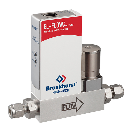
EL-FLOW® Prestige series
Thermal Mass Flow Meters/Controllers
Doc. no.: 9.17.084G
Date: 16-03-2018
ATTENTION
Please read this Instruction Manual carefully before installing and operating the instrument.
Not following the guidelines could result in personal injury and/or damage to the equipment.
Advertisement
Table of Contents

Subscribe to Our Youtube Channel
Related Manuals for BRONKHORST EL-FLOW Prestige series


Summary of Contents for BRONKHORST EL-FLOW Prestige series
- Page 1 Instruction Manual EL-FLOW® Prestige series Thermal Mass Flow Meters/Controllers Doc. no.: 9.17.084G Date: 16-03-2018 ATTENTION Please read this Instruction Manual carefully before installing and operating the instrument. Not following the guidelines could result in personal injury and/or damage to the equipment.
- Page 2 Subject to technical and optical changes as well as printing errors. The information contained in this document is subject to change at any time without prior notification. Bronkhorst High-Tech B.V. reserves the right to modify or improve its products and modify the contents without being obliged to inform any particular persons or organizations. The device specifications and the contents of the package may deviate from what is stated in this document.
- Page 3 Bronkhorst® Warranty Bronkhorst® products are warranted against defects in material and workmanship for a period of three years from the date of shipment, provided they are used in accordance with the ordering specifications and not subject to abuse or physical damage.
- Page 4 Bronkhorst® Instruction Manual EL-FLOW® Prestige 9.17.084G...
-
Page 5: Table Of Contents
Bronkhorst® Table of contents Introduction ......................7 . - Page 6 Bronkhorst® 3.8.3 Control mode - readout/change ......................28 3.8.4...
-
Page 7: Introduction
If you are planning to use the product (including any third party components supplied by Bronkhorst, such as pumps or valves) with other media and/or other conditions, always be sure to check the wetted materials (including seals) for compatibility. See the technical specifications of the product and consult third party documentation (if applicable) to check the incorporated materials. -
Page 8: Other Documents
RS232 communication, there are such options as RS485 communication, digital frequency/pulse output, alarm output/reset, valve purge/close and analog valve output. Furthermore Bronkhorst offers various integrated fieldbus options: DeviceNet™, PROFIBUS DP, Modbus RTU/ASCII, EtherCAT®, PROFINET and FLOW-BUS. -
Page 9: Model Key
Bronkhorst® Model key The model key on the product label contains information about the technical properties of the instrument as ordered. The specific properties can be retrieved with the diagram below. See section Customized I/O options (pin 5) for more information about the pin-5 configuration options. -
Page 10: Starting Up
The EL-FLOW® Prestige is fitted with specific sealing material(s), compatible with the media specified at ordering time. Be sure that the sealing materials are compatible with the media and conditions used in the system. Bronkhorst High-Tech B.V. cannot be held responsible for any damage resulting from the use of other media and/or conditions than specified on the purchase order. -
Page 11: Mounting
However, compliance with the EMC requirements is not possible without the use of proper cables and connector/gland assemblies. Bronkhorst recommends the use of their standard cables. These cables have the right connectors and if loose ends are used, these are marked to help prevent wrong connection. When using other cables, cable wire diameters should be sufficient to carry the supply current, and voltage loss must be kept as low as possible. -
Page 12: Analog / Digital Communication
E-8000. Connecting the instrument with an RS232 cable or an RS232 cable with a USB to RS232 converter to a PC enables the use of the (free) Bronkhorst® FlowWare software for Windows, such as FlowDDE and FlowPlot. Make sure that the instrument label indicates RS232 settings for the 9-pin sub-D connector and apply the proper baud rate settings. -
Page 13: Powering Up And Powering Down
2.12 Calibration The EL-FLOW® Prestige is factory calibrated. Bronkhorst certifies that the instrument meets the rated accuracy. Calibration is performed using measurement standards traceable to the Dutch Metrology Institute (VSL). Calibration certificates are included in the scope of delivery. -
Page 14: Basic Operation
Bronkhorst® Basic operation Mass flow measurement and control After correct installation of the EL-FLOW® Prestige Mass Flow Meter (MFM) or Mass Flow Controller (MFC) and when all safety precautions have been taken into account the instrument can immediately be used for measuring/ controlling the required flow rate in the system by means of the selected communication interface(s). -
Page 15: Valve Safe State
With FlowTune™ fixed fluid properties for any gas or mixture can be stored in the instrument (density, heat capacity, thermal conductivity and dynamic viscosity). Although custom fluid data can be used, Bronkhorst advises to use the FLUIDAT® on the Net website for calculation of fluid properties at the actual process conditions. FLUIDAT® is a collection of routines to calculate physical properties of gases and liquids. -
Page 16: Communication Interfaces
Bronkhorst® Communication interfaces Numerous input/output options can be installed on EL-FLOW® Prestige instruments via both the 9-pin sub-D connector on the side of the instrument and the optional fieldbus connector on top of the instrument. Analog and RS232 FLOW-BUS or Modbus PROFIBUS DP DeviceNet™... -
Page 17: Analog Operation
Bronkhorst® Model key 2. Fieldbus (top connector) (example: none) Customized I/O setting (pin 5) 4. Analog interface (pin 2, 3) (example: inactive setpoint source, measure always available) 5. Digital interface (pin 1, 6) (example: RS232, active setpoint source) 6. Side connector digital interface settings (protocol, medium, baud rate, parity) -
Page 18: Cabling
DeviceNet™. Keep in mind that the 9-pin sub-D configuration of a Bronkhorst® instrument differs from the 9-pin sub-D configuration of a PC COM-port. Make sure the correct cables are used for hook-up. When in doubt, always check the hook-up diagrams associated with the instruments. -
Page 19: Flowdde
3.4.2 FlowDDE Digital Bronkhorst® instruments can be operated via RS232 using the Bronkhorst® FlowDDE server application. Dynamic Data Exchange (DDE) provides a basic level of inter process communication between Windows applications. Together with a client application, either self-made or with a third party SCADA program, it is possible to create an easy way of data exchange between the flow meter/controller and a Windows application. -
Page 20: Software (Dde Applications)
MS-Office, LabVIEW, InTouch and Wizcon. Bronkhorst® software applications 'FlowView' (left) and 'FlowPlot' (right) FlowDDE and other Bronkhorst® applications are available on the support CD or can be downloaded from the product pages on the Bronkhorst website: www.bronkhorst.com/products 3.4.4 Baud rate setup EL-FLOW®... -
Page 21: Basic Rs485 Operation (Flow-Bus/Modbus)
9-pin sub-D side connector is set for FLOW-BUS or Modbus communication. The label on the back of the instrument indicates the factory settings of the connector pinning. FLOW-BUS FLOW-BUS is a Bronkhorst® designed fieldbus, based on RS485 technology, for digital communication between devices, offering the possibility of host-control by a Windows computer. Characteristics: ·... -
Page 22: Cabling
Bronkhorst® 3.5.1 Cabling The illustrations below show examples of a number of EL-FLOW® Prestige instruments in an RS485 bus system. Note that many other bus configurations are possible, contact your local sales representative for more information. Please check the total power consumption of your instruments and do not exceed the maximum power of the power supply. -
Page 23: Software
When using a Windows computer to communicate with EL-FLOW® Prestige instruments, only the FLOW-BUS protocol is supported by Bronkhorst® software. When using Modbus operation, software from third parties, such as LabVIEW, ModScan or a Modbus PLC must be used to serve as Modbus master. -
Page 24: Other Fieldbus Configurations
The DeviceNet™ interface offers a direct connection to a DeviceNet™ network, according to the mass flow controller profile specified by the ODVA. The Bronkhorst® DeviceNet™ instrument is a Group 2 Only Server device whose messages comply with the Controlled Area Network (CAN) 2.0A standard and with the DeviceNet™ protocol. -
Page 25: Led Indications
Changing EtherCAT® Second Address EtherCAT® supports the use of a Second Address. Bronkhorst® instruments have 3 rotary switches, with which a Second Address can be set in the range of 0 – 4095 (0xFFF). This value of the rotary switches will be copied to the Configured Station Alias register (address 0x0012:0x0013) at instrument start-up. -
Page 26: Micro Switch Functions
Bronkhorst® • Pattern Time Indication continuous No error continuous Critical error; the instrument needs servicing before it can be used short flash 0.1 sec on, FLOW-BUS Node occupied: re-install instrument 2 sec off No data exchange between master and slave (automatic recovery) -
Page 27: Normal Operating Functions
Bronkhorst® 3.8.1 Normal operating functions · In order to access these functions, press and hold the switch while the instrument is in normal operation mode (green LED glowing). · The available functions are presented in a repeating sequence of patterns, where each pattern indicates a function. -
Page 28: Control Mode - Readout/Change
Bronkhorst® 3.8.3 Control mode - readout/change Reading control mode · By briefly pressing the switch 2 times with intervals of up to 1 second in normal operation mode, the instrument shows its current control mode with a series of consecutive LED indication patterns. - Page 29 Bronkhorst® Examples: · for node address 35, the green LED will flash 3 times and the red LED 5 times · for node address 116, the green LED will flash 11 times and the red LED 6 times On DeviceNet™ the node address is called MAC ID.
-
Page 30: Basic Parameters And Properties
Bronkhorst® Basic parameters and properties This section describes the most common parameters for digital communication with the instrument. Digital parameters are most easily accessible via FlowPlot or FlowView software or a Bronkhorst® readout and control unit (E-8000 or BRIGHT). 3.9.1 General This section describes the most commonly used parameters for operating the EL-FLOW®... -
Page 31: Measurement And Control (Basic)
R 113/3 0xF118…0xF11F/ 61721…61728 Instrument serial number for identification. BHT Model Number Type Access Range FlowDDE FLOW-BUS Modbus Unsigned char[35] RW 113/2 0xF110…0xF117/ 61713…61720 This parameter shows the Bronkhorst® instrument model type information. 9.17.084G Instruction Manual EL-FLOW® Prestige... -
Page 32: Alarms And Counter
3.9.4 Alarms and counter Alarm and counter settings are most easily accessible via FlowPlot or FlowView software or a Bronkhorst® readout and control unit (E-8000 or BRIGHT). For more information about the alarm and counter parameters, see the according sub sections under... -
Page 33: Digital Procedure
Bronkhorst® 3.10.2 Digital procedure FlowPlot provides an easy way to adjust the zero point of an instrument via RS232; the Auto zero function automatically performs the procedure described below. To re-adjust the zero point using digital communication (RS232 or fieldbus), set parameter values in the following sequence:... -
Page 34: Advanced Operation
Bronkhorst® Advanced operation Sealing material compatibility EL-FLOW® Prestige instruments are fitted from factory with internal seals compatible with the requested gas type. If another gas or mixture is used, always make sure that the gas or mixture is compatible with the used sealing materials. As a factory standard, the instruments are provided with Viton®... -
Page 35: Advanced Parameters And Properties
Bronkhorst® Advanced parameters and properties 4.2.1 Measurement and control (advanced) Fmeasure Type Access Range FlowDDE FLOW-BUS Modbus Float -3.4E+38… 33/0 0xA100…0xA101/ 41217…41218 3.4E+38 Floating point variant of Measure. Fmeasure shows the measured value in the capacity and capacity unit for which the instrument has been set. -
Page 36: Special Parameters
Bronkhorst® 4.2.2 Special parameters Init Reset Type Access Range FlowDDE FLOW-BUS Modbus Unsigned char 82/64 0/10 0x000A/11 Init Reset is used to unlock secured parameters (designated by a symbol) for writing. This parameter can be set to the following values:... -
Page 37: Fluid Set
Consult Bronkhorst service personnel when in doubt. - Page 38 Bronkhorst® Capacity Type Access Range FlowDDE FLOW-BUS Modbus Float RW 1E-10… 1/13 0x8168…0x8169/33129…33130 1E+10 This parameter sets the maximum readout/control value (100%) for the selected fluid set in readout units corresponding to Capacity Unit. Capacity Unit Type Access Range...
- Page 39 Bronkhorst® Temperature Type Access Range FlowDDE FLOW-BUS Modbus Float -250…500 33/7 0xA138…0xA139/41273…41274 Indication of the actual media temperature in °C. Pressure Type Access Range FlowDDE FLOW-BUS Modbus Float 0…3.4E+38 33/8 0xA140…0xA141/41281…41282 Indication of the actual (inlet) pressure in bar(a). By default the value of this parameter is equal to the value of Inlet pressure.
- Page 40 Bronkhorst® Viscosity Type Access Range FlowDDE FLOW-BUS Modbus Float RW 0…3.4E+38 113/21 0xF1A8…0xF1A9/61865…61866 (Fixed) dynamic viscosity for the selected fluid set in Pa·s. Mix Fraction Type Type Access Range FlowDDE FLOW-BUS Modbus Unsigned char RW 0…2 126/4 0x0FC4/4037...
-
Page 41: Alarms
Bronkhorst® 4.2.4 Alarms Alarm settings are most easily accessible via FlowPlot or FlowView or a Bronkhorst® readout and control unit. The built-in alarm functionality can be used to handle different alarm types: · system errors and warnings · min/max alarms ·... - Page 42 Bronkhorst® Alarm Maximum Limit Type Access Range FlowDDE FLOW-BUS Modbus Unsigned int 0…32000 97/1 0x0C21/3106 Maximum limit for Measure to activate the maximum alarm situation (after Alarm Delay Time). Range 0…32000 represents 0… 100% signal. Alarm Maximum Limit must be greater than Alarm Minimum Limit.
-
Page 43: Counter
Bronkhorst® 4.2.5 Counter Counter settings are most easily accessible via FlowPlot or FlowView or a Bronkhorst® readout and control unit. Counter Mode Type Access Range FlowDDE FLOW-BUS Modbus Unsigned char 0…2 104/8 0x0D08/3337 Available modes: Value Description Counter off (default) -
Page 44: Network Configuration
Bronkhorst® Counter New Setpoint Type Access Range FlowDDE FLOW-BUS Modbus Unsigned int 0…32000 104/6 0x0D06/3335 New (safe) setpoint when a counter limit is reached until reset. Range 0…32000 represents 0…100% setpoint. Default value: 0 Reset Counter Enable Type Access Range... -
Page 45: Master/Slave Configuration (Flow-Bus)
Bronkhorst® Communication via power supply connection (RS232/RS485) Use the following parameters to configure the instrument for communication via the 9-pin D-sub connector on the side of the instrument: If the 9-pin D-sub (power) connector is set for RS485 communication, the instrument will not respond when connected to an RS232 configuration. -
Page 46: Special Features
Bronkhorst® Slave Factor Type Access Range FlowDDE FLOW-BUS Modbus Float 0…500 33/1 0xA108…0xA109/41225…41226 The controller output from the master instrument is multiplied by Slave Factor/100% to get the slave instrument setpoint. In systems other than FLOW-BUS via RS485, Slave Factor is effective only if Control Mode is set to 'Analog slave', and the analog output signal of the master instrument is redirected to the input of the slave instrument. - Page 47 Bronkhorst® Code Description For factory selected digital control (…-D#-C5S): If parameter Control mode is set for digital control by factory, the setpoint threshold for activating the device connected to pin 5 is any value > 0. Note: If the instrument is forced into Valve Safe State, the digital output is not affected, so a (n/c) shut-off valve connected to pin 5 will not close when the (n/c) controller is in Valve Safe State’...
-
Page 48: Changing Default Control Mode
Bronkhorst® Code Description Digital input, reset counter The counter resets when pin 5 is connected to 0 Vdc. Example for I1R or I2R hook-up Digital input, reset alarm The alarm resets when pin 5 is connected to 0 Vdc. 4.3.2... -
Page 49: Troubleshooting And Service
Micro switch functions) · with the restore function of a Bronkhorst® readout and control unit (BRIGHT, E-8000) · via RS232 communication, with the Restore settings function in FlowPlot To restore the factory settings using the multifunctional switch, follow these instructions: 1. -
Page 50: Common Issues
Bronkhorst® Common issues Symptom Possible cause Action No power (LEDs not burning) No power supply Check power supply Check cable connection Internal fuse blown due to long lasting Return to factory shortage Zero output signal No setpoint accepted, incorrect control... -
Page 51: Service
Bronkhorst® Service For current information on Bronkhorst® and service addresses, please visit our website: http://www.bronkhorst.com Do you have any questions about our products? Our Sales Department will gladly assist you selecting the right product for your application. Contact sales by e-mail: ›... -
Page 52: Removal And Return Instructions
Service & Support section of the Bronkhorst website (www.bronkhorst.com). Important: Clearly note, on top of the package, the customs clearance number of Bronkhorst High-Tech B.V., namely: NL801989978B01 (only if applicable, otherwise contact your distributor for local arrangements.) Instruction Manual EL-FLOW®... - Page 53 Bronkhorst® Mix Component Fraction Parameter index Mix Component Index Mix Fraction Type Parameters Mix Volume Pressure Parameters - Alarms Mix Volume Temperature Alarm Delay Time Parameters - Master/Slave Alarm Info Master Node Alarm Maximum Limit Slave Factor Alarm Minimum Limit...
Need help?
Do you have a question about the EL-FLOW Prestige series and is the answer not in the manual?
Questions and answers