Table of Contents
Advertisement
Quick Links
SRX3600 Services Gateway Getting
Started Guide
January 2011
Part Number: 530-038205
Revision 01
Contents
Copyright © 2011, Juniper Networks, Inc.
About This Guide . . . . . . . . . . . . . . . . . . . . . . . . . . . . . . . . . . . . . . . . . . . . . . . . . . . . 3
Step 1: Prepare the Site for SRX3600 Services Gateway Installation . . . . . . . . . . . 5
Rack Mounting Requirements . . . . . . . . . . . . . . . . . . . . . . . . . . . . . . . . . . . . . . 5
Tools Required to Unpack and Prepare the SRX3600 Services Gateway for
Installation . . . . . . . . . . . . . . . . . . . . . . . . . . . . . . . . . . . . . . . . . . . . . . . . . . 5
Open-Frame Rack . . . . . . . . . . . . . . . . . . . . . . . . . . . . . . . . . . . . . . . . . . . . . . . . 6
Step 3: Install the Services Gateway . . . . . . . . . . . . . . . . . . . . . . . . . . . . . . . . . . . . . 7
Install the Services Gateway Using a Mechanical Lift . . . . . . . . . . . . . . . . . . . . 8
Install the Device Without Using a Mechanical Lift . . . . . . . . . . . . . . . . . . . . . 10
Remove Components . . . . . . . . . . . . . . . . . . . . . . . . . . . . . . . . . . . . . . . . 10
Lift the Chassis into the Rack . . . . . . . . . . . . . . . . . . . . . . . . . . . . . . . . . . . 12
Reinstall Components . . . . . . . . . . . . . . . . . . . . . . . . . . . . . . . . . . . . . . . . 13
Step 4: Connect the Grounding Cable . . . . . . . . . . . . . . . . . . . . . . . . . . . . . . . . . . . 13
Step 5: Connect the External Devices and IOC Cables . . . . . . . . . . . . . . . . . . . . . . 14
Connect to a Network for Out-of-Band Management . . . . . . . . . . . . . . . . . . . 14
Connect a Management Console . . . . . . . . . . . . . . . . . . . . . . . . . . . . . . . . . . . 15
Connect the IOC Cables . . . . . . . . . . . . . . . . . . . . . . . . . . . . . . . . . . . . . . . . . . 16
Step 6: Connect Power Cables . . . . . . . . . . . . . . . . . . . . . . . . . . . . . . . . . . . . . . . . . 16
Connect Power to an AC-Powered Services Gateway . . . . . . . . . . . . . . . . . . . 17
Connect Power to a DC-Powered Services Gateway . . . . . . . . . . . . . . . . . . . . 18
Step 7: Perform the Initial Software Configuration . . . . . . . . . . . . . . . . . . . . . . . . . 20
Enter Configuration Mode . . . . . . . . . . . . . . . . . . . . . . . . . . . . . . . . . . . . . . . . 20
Configure User Accounts and Passwords . . . . . . . . . . . . . . . . . . . . . . . . . . . . 20
Configure System Attributes . . . . . . . . . . . . . . . . . . . . . . . . . . . . . . . . . . . . . . . 21
Commit the Configuration . . . . . . . . . . . . . . . . . . . . . . . . . . . . . . . . . . . . . . . . 22
Safety Warnings . . . . . . . . . . . . . . . . . . . . . . . . . . . . . . . . . . . . . . . . . . . . . . . . . . . . 24
Canada . . . . . . . . . . . . . . . . . . . . . . . . . . . . . . . . . . . . . . . . . . . . . . . . . . . . . . . 26
European Community . . . . . . . . . . . . . . . . . . . . . . . . . . . . . . . . . . . . . . . . . . . . 26
1
Advertisement
Table of Contents

Related Manuals for Juniper SRX3600


Summary of Contents for Juniper SRX3600
-
Page 1: Table Of Contents
About This Guide ........... . 3 Step 1: Prepare the Site for SRX3600 Services Gateway Installation ... 5 Rack Mounting Requirements . - Page 2 United States ........... 27 SRX3600 Services Gateway NEBS and ETSI Compliance ....27 SRX3600 Services Gateway NEBS and ETSI Standards .
-
Page 3: About This Guide
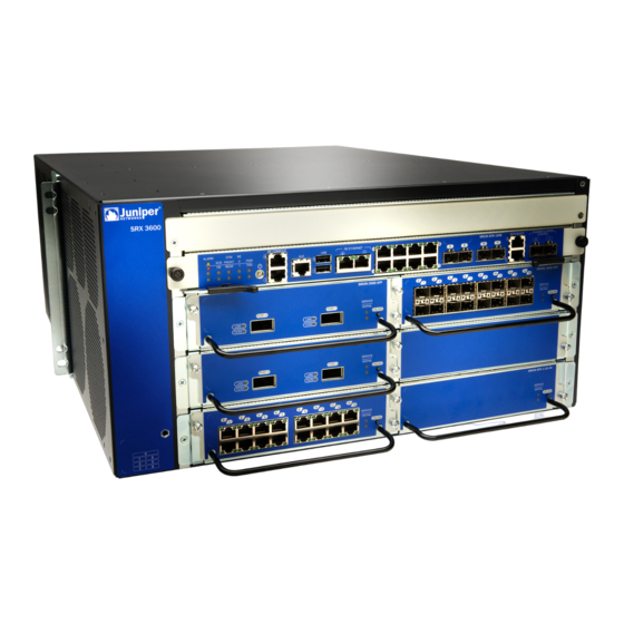
Routing Engine, one slot for an SRX Clustering Module (SCM), four slots for power supplies, and one slot for the fan tray and air filter. Figure 1 on page 3 and Figure 2 on page 4 show the front and rear of the SRX3600 Services Gateway. - Page 4 By installing different combinations of IOCs and SPCs, you can tailor both the number of network ports and the maximum security processing capacity to suit your network. Table 1 on page 4 describes the minimum system configuration for the SRX3600 Services Gateway.
-
Page 5: Step 1: Prepare The Site For Srx3600 Services Gateway Installation
When mounting the services gateway in a partially filled rack, load the rack from the bottom to the top, with the heaviest component at the bottom of the rack. Tools Required to Unpack and Prepare the SRX3600 Services Gateway for Installation To unpack the services gateway and prepare for installation, you need the following tools: Copyright ©... -
Page 6: Step 2: Install The Mounting Hardware In A Four-Post Rack Or Cabinet Or An Open-Frame Rack
SRX3600 Services Gateway Getting Started Guide A mechanical lift—recommended Phillips screwdrivers, numbers 1 and 2 Electrostatic discharge (ESD) wrist strap Antistatic mat Proceed to “Step 2: Install the Mounting Hardware in a Four-Post Rack or Cabinet or an Open-Frame Rack” on page 6. -
Page 7: Step 3: Install The Services Gateway
The procedure for installing the services gateway depends on whether you use a mechanical lift: Install the Services Gateway Using a Mechanical Lift on page 8 Install the Device Without Using a Mechanical Lift on page 10 Copyright © 2011, Juniper Networks, Inc. -
Page 8: Install The Services Gateway Using A Mechanical Lift
Ensure that the rack is in its permanent location and is secured to the building. Ensure that the installation site allows adequate clearance for both airflow and maintenance. For details, see the SRX3600 Services Gateway Hardware Guide. Load the services gateway onto the lift, making sure it rests securely on the lift platform (see Figure 6 on page 8). - Page 9 Proceed to “Step 4: Connect the Grounding Cable” on page 13. Copyright © 2011, Juniper Networks, Inc.
-
Page 10: Install The Device Without Using A Mechanical Lift
SRX3600 Services Gateway Getting Started Guide Install the Device Without Using a Mechanical Lift To install the services gateway without a mechanical lift: Remove Components on page 10 Lift the Chassis into the Rack on page 12 Reinstall Components on page 13... - Page 11 Attach an electrostatic discharge (ESD) grounding strap to your bare wrist, and connect the strap to one of the ESD points on the chassis. For more information about ESD, see the SRX3600 Services Gateway Hardware Guide. Release each component by loosening its retaining screws and unlatching its ejector handles as appropriate.
-
Page 12: Lift The Chassis Into The Rack
SRX3600 Services Gateway Getting Started Guide Lift the Chassis into the Rack Lifting the chassis and mounting it in a rack requires two people. The empty chassis weighs approximately 43.6 lb (19.8 kg). Ensure that the rack is in its permanent location and is secured to the building. -
Page 13: Reinstall Components
Connect the ESD grounding strap to one of the ESD points on the chassis. For more information about ESD, see the SRX3600 Services Gateway Hardware Guide. Place the grounding cable lug over the grounding point. The grounding point is sized for M5 screws. -
Page 14: Step 5: Connect The External Devices And Ioc Cables
SRX3600 Services Gateway Getting Started Guide Figure 12: Connecting the Grounding Cable Secure the grounding cable lug to the chassis, first with the washers, and then with the screws. Dress the grounding cable and verify that it does not touch or block access to services gateway components, and that it does not drape where people could trip on it. -
Page 15: Connect A Management Console
SFB as shown in Figure 14 on page 15. Figure 14: Connect Management Console Cable RE CONS OLE ALAR M SCB FRON T HA REAR Plug the female DB-9 end into the device’s serial port. Copyright © 2011, Juniper Networks, Inc. -
Page 16: Connect The Ioc Cables
SRX3600 Services Gateway Getting Started Guide Connect the IOC Cables Have ready a length of the type of cable used by the IOC. For cable specifications, see the SRX3600 Services Gateway Hardware Guide. If the cable connector port is covered by a rubber safety plug, remove the plug. -
Page 17: Connect Power To An Ac-Powered Services Gateway
Attach an electrostatic discharge (ESD) grounding strap to your bare wrist, and connect the strap to one of the ESD points on the chassis. For more information about ESD, see the SRX3600 Services Gateway Hardware Guide. Locate the power cords you will use to connect the device to AC power. See the SRX3600 Services Gateway Hardware Guide for specifications. -
Page 18: Connect Power To A Dc-Powered Services Gateway
SRX3600 Services Gateway Getting Started Guide Figure 15: Connecting AC Power to the Services Gateway If sufficient power is available and the AC power supply is correctly installed, the power supply powers up automatically. If the AC power supply is installed correctly, the LED on the Switch Fabric Board (SFB) lights steadily. - Page 19 Attach an electrostatic discharge (ESD) grounding strap to your bare wrist, and connect the strap to one of the ESD points on the chassis. For more information about ESD, see the SRX3600 Services Gateway Hardware Guide. For each power supply: Remove the clear plastic cover protecting the terminal studs on the faceplate.
-
Page 20: Step 7: Perform The Initial Software Configuration
SRX3600 Services Gateway Getting Started Guide Switch on the external circuit breakers to provide voltage to the DC power source cable leads. If sufficient power is available and the DC power supply is correctly installed, the power supply will power up automatically. If the DC power supply is installed correctly and functioning normally, the LED on the SFB lights steadily. -
Page 21: Configure System Attributes
Check the configuration for validity. [edit] admin@# commit check configuration check succeeds Copyright © 2011, Juniper Networks, Inc. -
Page 22: Commit The Configuration
SRX3600 Services Gateway Getting Started Guide Commit the Configuration Optionally, display the configuration to verify that it is correct. admin@# show ## Last changed: 2008-05-07 22:43:25 UTC version "9.2I0 [builder]"; system { autoinstallation; host-name henbert; root-authentication { encrypted-password "$1$oTVn2KY3$uQe4xzQCxpR2j7sKuV.Pa0"; ##... - Page 23 { from-zone trust to-zone untrust { policy bob { match { source-address any; destination-address any; application any; then { permit; Commit the configuration to activate it on the services gateway. [edit] admin@# commit Copyright © 2011, Juniper Networks, Inc.
-
Page 24: Safety Warnings
AC input of the services gateway. Only trained and qualified personnel should install or replace the services gateway. Perform only the procedures described in this guide or the SRX3600 Services Gateway Hardware Guide. Other services should be performed by authorized service personnel only. - Page 25 Safety Warnings Before installing the services gateway, read the guidelines for site preparation in the SRX3600 Services Gateway Hardware Guide to make sure that the site meets power, environmental, and clearance requirements for the services gateway. For the cooling system to function properly, the airflow around the chassis must be unrestricted.
-
Page 26: Srx3600 Services Gateway Compliance Statements For Emc Requirements
SRX3600 Services Gateway Getting Started Guide WARNING: The attached power cable is only for this product. Do not use the cable for another product. SRX3600 Services Gateway Compliance Statements for EMC Requirements Canada on page 26 European Community on page 26... -
Page 27: United States
ETSI 300019-2-3 GR-1089-CORE SRX3600 Services Gateway NEBS and ETSI Configuration Requirements To meet the NEBS and ETSI standards described in “SRX3600 Services Gateway NEBS and ETSI Standards” on page 27, the SRX3600 Services Gateway must be configured as follows: The services gateway must be installed in accordance with the instructions and procedures in the SRX3600 Services Gateway Hardware Guide. -
Page 28: Srx Series Documentation And Release Notes
SRX3600 Services Gateway Getting Started Guide Figure 17: Power Supply Model and Revision Label (AC Shown, DC Similar) DS1200-3-401 REV: 0F For DC-powered services gateways, all four power supplies installed in the services gateway must be enhanced DC power supplies. You can determine the power supply type by using the show chassis hardware command. -
Page 29: Requesting Technical Support
7 days a week, 365 days a year. Self-Help Online Tools and Resources For quick and easy problem resolution, Juniper Networks has designed an online self-service portal called the Customer Support Center (CSC) that provides you with the following features: Find CSC offerings: http://www.juniper.net/customers/support/... -
Page 30: Revision History
Products made or sold by Juniper Networks or components thereof might be covered by one or more of the following patents that are owned by or licensed to Juniper Networks: U.S. Patent Nos. 5,473,599, 5,905,725, 5,909,440, 6,192,051, 6,333,650, 6,359,479, 6,406,312, 6,429,706, 6,459,579, 6,493,347, 6,538,518, 6,538,899, 6,552,918, 6,567,902, 6,578,186, and 6,590,785.
Need help?
Do you have a question about the SRX3600 and is the answer not in the manual?
Questions and answers