Tektronix ECO8000 Series Service Manual
Automatic changeover unit
Hide thumbs
Also See for ECO8000 Series:
- User manual (124 pages) ,
- User manual (117 pages) ,
- Instructions manual (25 pages)

Related Manuals for Tektronix ECO8000 Series


Summary of Contents for Tektronix ECO8000 Series
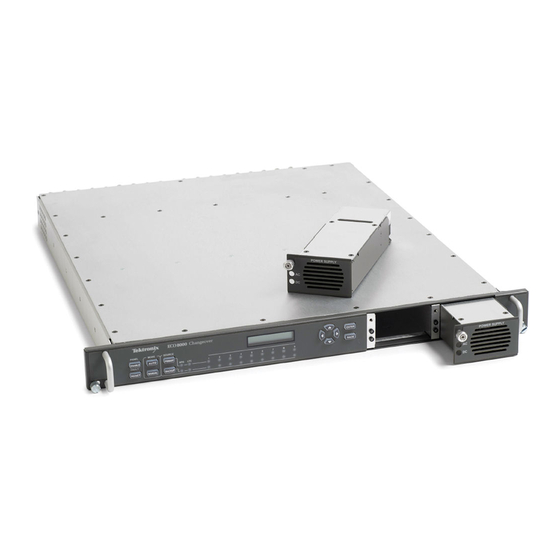
- Page 1 ECO8000 Series Automatic Changeover Unit Service Manual *P077088000* 077-0880-00...
- Page 3 ECO8000 Series Automatic Changeover Unit Service Manual Register now! Click the following link to protect your product. ► www.tektronix.com/register www.tektronix.com 077-0880-00...
- Page 4 Copyright © Tektronix. All rights reserved. Licensed software products are owned by Tektronix or its subsidiaries or suppliers, and are protected by national copyright laws and international treaty provisions. Tektronix products are covered by U.S. and foreign patents, issued and pending. Information in this publication supersedes that in all previously published material.
- Page 5 Tektronix, with shipping charges prepaid. Tektronix shall pay for the return of the product to Customer if the shipment is to a location within the country in which the Tektronix service center is located. Customer shall be responsible for paying all shipping charges, duties, taxes, and any other charges for products returned to any other locations.
-
Page 7: Table Of Contents
Main board ....................Processor board ....................Channel modules..................... Front Panel assembly..................Power Supply modules ..................Combiner board ....................Maintenance Maintenance....................... Preventing ESD ....................Inspection and cleaning ..................Remove and replace procedures ................Repackaging instructions ................. 3-25 ECO8000 Series Service Manual... - Page 8 Check that the channel is enabled ..............4-21 Disable the Relay Check function for an HREF/Relay channel ......... 4-22 Execute the Initialize Hardware function ............4-23 Replaceable Parts Replaceable parts ....................Parts ordering information .................. Using the replaceable parts lists................Index Index ECO8000 Series Service Manual...
- Page 9 List of Figures Figure 1-1: Location of rear panel power connectors (ECO8000 shown) ......... Figure 2-1: ECO8000 Series subsystems (ECO8020 with Option DPW shown) ......Figure 2-2: ECO8000 Series high-level block diagram ............Figure 3-1: Installing or removing the instrument into or from the rack ........
- Page 10 Table 4-4: Power off LED states for a Power Supply module..........Table 5-1: Front panel assembly and Power Supply module replaceable parts list ....... Table 5-2: Main chassis and ECO8000 rear panel replaceable parts list ........Table 5-3: ECO8020 rear panel replaceable parts list ............ECO8000 Series Service Manual...
-
Page 11: Important Safety Information
Read the safety sections of the other component manuals for warnings and cautions related to operating the system. When incorporating this equipment into a system, the safety of that system is the responsibility of the assembler of the system. ECO8000 Series Service Manual... - Page 12 Do not operate in wet/damp conditions. Be aware that condensation may occur if a unit is moved from a cold to a warm environment. Do not operate in an explosive atmosphere. Keep product surfaces clean and dry. Remove the input signals before you clean the product. ECO8000 Series Service Manual...
-
Page 13: Service Safety Summary
Be sure your work area meets applicable ergonomic standards. Consult with an ergonomics professional to avoid stress injuries. Use only the Tektronix rackmount hardware specified for this product. Service safety summary The Service safety summary section contains additional information required to safely perform service on the product. -
Page 14: Terms In This Manual
find out the nature of the potential hazards and any actions which have to be taken to avoid them. (This symbol may also be used to refer the user to ratings in the manual.) The following symbol(s) may appear on the product: viii ECO8000 Series Service Manual... -
Page 15: Preface
Contact your local Tektronix representative for information on where to return your instrument if it requires repair during the warranty period. To prevent personal injury or damage to the ECO8000 Series, consider the following before beginning service: The procedures in this manual should be performed only by a qualified service person. -
Page 16: Manual Structure And Conventions
Names of front panel controls and menus appear in the same case (initial capitals, all uppercase, etc.) in the manual as is used on the ECO8000 Series front panel and menus. -
Page 17: Product Documentation
ECO8000 Series Release Notes issues (Tektronix part number 077-0878-00) Software licenses The software licenses used by the ECO8000 Series are available for download from the Tektronix Web site. The licenses are bundled with the product firmware package. ECO8000 Series Service Manual... - Page 18 Preface ECO8000 Series Service Manual...
-
Page 19: Operating Basics
Operating basics... -
Page 21: Production Description
Operating basics Production description The ECO8000 Series Automatic Changeover Unit is a highly versatile automatic sync and signal changeover unit with configurations and capabilities required to address modern master sync application and other advanced sync timing application. The ECO8000 Series offers exceptional reliability, stability, and is designed with optional high-bandwidth input changeover capabilities for HD/SD and/or 3G-SDI signal environments. -
Page 22: Operation Information
(See page xi, Product documentation.) Power connection The ECO8000 Series operates from a single-phase power source with the neutral conductor at or near earth ground. The line conductor is fused for over-current protection. A protective ground connection through the grounding conductor in the locking power cord is essential for safe operation. -
Page 23: Overview Of Instrument Operation
The number of right-arrow characters represents the number of times you need to press the BACK button to return to the top-level menu. ECO8000 Series Service Manual 1–3... -
Page 24: Web User Interface
STATUS menu. Web User Interface The ECO8000 Series has a 10/100 BASE-T Ethernet port on the rear panel that allows you to use a PC to remotely control the instrument. When the Web Interface is enabled in the SYSTEM CONFIG menu, enter the IP address of the instrument in a supported Web browser to open the ECO8000 Web Interface. -
Page 25: Upgrades
Hardware upgrade. There are no hardware upgrades available for the ECO8000 Series. Firmware upgrade. Tektronix releases software and firmware updates for products to add new features and to fix product problems. You can find the latest firmware for your product at the Tektronix Web site (www.tektronix.com/downloads). - Page 26 Operating basics 1–6 ECO8000 Series Service Manual...
-
Page 27: Theory Of Operation
Theory of operation... -
Page 29: Instrument Level
Theory of operation This section describes the basic operation of the major circuit blocks or modules in the ECO8000 Series instruments. The block diagram shows the modules and functional blocks in the instrument. (See Figure 2-2.) Instrument level The ECO8000 and ECO8020 have three major subsystems which are essentially... - Page 30 As indicated in the high-level block diagram (See Figure 2-2.), the ECO8000 Series implements these subsystems with the following boards and modules: Main board Processor board Channel modules, either REF/ELSW or HREF/Relay Front Panel module Power supply module(s) Combiner board 2–2 ECO8000 Series Service Manual...
-
Page 31: Figure 2-2: Eco8000 Series High-Level Block Diagram
Theory of operation Figure 2-2: ECO8000 Series high-level block diagram ECO8000 Series Service Manual 2–3... -
Page 32: Main Board
The pin-out of the DSUBs are compatible with the LTC outputs on the SPG8000 and GPS7 module of the TG8000, which allows the instruments to connect together with a standard cable. 2–4 ECO8000 Series Service Manual... -
Page 33: Processor Board
The Processor board has a battery to power the real-time clock. No other functions are dependent on the battery. The battery voltage is nominally 3 V and can be checked from the Diagnostics menu, with threshold levels of >40%, between 20 and 40%, and less than 20%. ECO8000 Series Service Manual 2–5... -
Page 34: Channel Modules
Finally there are four module ID bits which have resistors to pull up or down to indicate the type of module (REF/ELSW or HREF/Relay) and the number of channels (three or five). 2–6 ECO8000 Series Service Manual... -
Page 35: Front Panel Assembly
PLD on the Main board. The PLD shifts the drive level for each LED into the drivers, then latches the levels in to drive each output. ECO8000 Series Service Manual 2–7... -
Page 36: Power Supply Modules
The Power Module board has an I2C bus for the memory and temperature sensor. The I2C pins in the connector are shorter so that ground and power are applied first when the module is installed. 2–8 ECO8000 Series Service Manual... -
Page 37: Combiner Board
The Combiner board also drives the fans and senses if they are not spinning. The fans are located in each Power Supply module. ECO8000 Series Service Manual 2–9... - Page 38 Theory of operation 2–10 ECO8000 Series Service Manual...
-
Page 39: Maintenance
Maintenance... - Page 41 Included are instructions for operating the diagnostic routines and troubleshooting trees. Most of the trees make use of the internal diagnostic routines to speed fault isolation to a module. Repackaging instructions – Information on returning an instrument for service. ECO8000 Series Service Manual 3–1...
-
Page 42: Preventing Esd
Handle circuit boards by the edges when possible. Do not touch module components or connector pins. Do not slide the circuit boards or modules over any surface. Avoid handling circuit boards in areas that have a floor or work-surface covering capable of generating a static charge. 3–2 ECO8000 Series Service Manual... -
Page 43: Inspection And Cleaning
Missing items or parts of items, bent Repair or replace damaged or pins, broken or frayed cables, and missing items, frayed cables, damaged connectors and defective modules Cracks Replace the LCD assembly Dirty Clean with glass cleaner ECO8000 Series Service Manual 3–3... -
Page 44: Table 3-2: Internal Inspection Checklist
Use a glass cleaner to clean the LCD. For the rest of the instrument, use a 75% isopropyl alcohol solution as a cleaner and rinse with deionized water. Before using any other type of cleaner, consult your Tektronix Service Center or representative. - Page 45 4. Gain access to the parts to be cleaned by removing easily accessible shields and panels. 5. Spray wash dirty parts with the isopropyl alcohol and wait 60 seconds for the majority of the alcohol to evaporate. 6. Dry all parts with low-pressure, deionized air. ECO8000 Series Service Manual 3–5...
-
Page 46: Remove And Replace Procedures
To clip cable ties ECO8000 Series Specifications and To perform the verification checks after Performance Verification manual (Tektronix reassembling part number 077-0876-XX) and all test equipment listed within Available for download from the Tektronix Web site at www.tektronix.com/manuals 3–6 ECO8000 Series Service Manual... -
Page 47: Figure 3-1: Installing Or Removing The Instrument Into Or From The Rack
Tilt both lever handles upward simultaneously to allow them to clear the stops. d. Pull the instrument past the stops and out of the rack. Figure 3-1: Installing or removing the instrument into or from the rack ECO8000 Series Service Manual 3–7... -
Page 48: Figure 3-2: Removing The Top Cover
4. Use the screwdriver handle with a P2 driver bit to remove the instrument top cover (reassembly torque: 4.0 in/lb.) Figure 3-2: Removing the top cover 3–8 ECO8000 Series Service Manual... - Page 49 Installing the top cover: Install the top cover screws in the following order: install group one screws, then group two screws, then group three screws. Do not tighten the screws until all are installed. Torque: 4.0 in/lb. ECO8000 Series Service Manual 3–9...
-
Page 50: Figure 3-3: Board Locator And Cable Routing Diagram
3. Lift the back edge of the Processor board slightly and carefully pull away from the rear panel to disconnect the Processor board from the main board. Reassembly. Reassemble in the reverse order of the disassembly procedure. 3–10 ECO8000 Series Service Manual... -
Page 51: Figure 3-4: Removing The Cable Tie
1. Clip or cut the cable-tie that is securing the two power cables from the rear-panel line filters. modules Figure 3-4: Removing the cable tie 2. Disconnect the black multi-wire cables between the Main board and any channel modules. Figure 3-5: Removing the multi-wire channel cables ECO8000 Series Service Manual 3–11... -
Page 52: Figure 3-6: Removing The Circuit Board Support Bracket
You can remove each module individually. Channel module Connector type Connector removal tool ECO8000: REF/ELSW, 9/16 inch deep nut driver HREF/Relay Reassembly torque: 14 in/lb. ECO8020: REF/ELSW, HD BNC P2 screwdriver HREF/Relay Reassembly torque: 4.0 in/lb. 3–12 ECO8000 Series Service Manual... -
Page 53: Figure 3-7: Removing The Bnc Nuts From A Channel Module
Maintenance Figure 3-7: Removing the BNC nuts from a channel module Figure 3-8: Removing a channel module ECO8000 Series Service Manual 3–13... -
Page 54: Figure 3-9: Installing Channel Cable Example: Slot 1 On The Main Board To The Channel 1 Module
The key is near pin 60 on the cable, so be sure to align the cable correctly on both ends. CAUTION. The channel modules will be damaged when power is applied if the cables are installed backwards in the connector. 3–14 ECO8000 Series Service Manual... - Page 55 5. Clip or cut the cable-tie that secures the two power cables from the rear-panel line filters. (See Figure 3-4.) 6. Disconnect the two power cables from J10 and J20 on the Combiner board. (See Figure 3-14 on page 3-20.) ECO8000 Series Service Manual 3–15...
-
Page 56: Figure 3-10: Disconnecting The Main Board Power Cable From The Combiner Board
10. Disconnect the white power cable from the Main board. 11. On the rear panel, use a 3/16 inch nut driver to remove the eight Main board connector post screws (reassembly torque: 4.0 in/lb.). 3–16 ECO8000 Series Service Manual... -
Page 57: Figure 3-11: Threading The Power Cables Through The Circuit Board Support Bracket
Main board is installed under the slot 1 Channel board. Cable routing: Route the three power cables through the slots in the support bracket. Figure 3-11: Threading the power cables through the circuit board support bracket ECO8000 Series Service Manual 3–17... -
Page 58: Figure 3-12: Positioning The Support Bracket Tabs With The Circuit Boards
Main board to the channel 1 board (above the Main board), routing the channel 1 cable below the white power cable. Install any other channel board cables: Slot 2 cable connects to the channel 2 board, and so on.(See Figure 3-5 on page 3-11.) 3–18 ECO8000 Series Service Manual... -
Page 59: Figure 3-13: Installing The Channel 1 Board Cable (Slot 1 To Channel 1 Board)
The key is near pin 60 on the cable, so be sure to align the cable correctly on both ends. CAUTION. The channel circuit boards will be damaged when power is applied if the cables are installed backwards in the connector. ECO8000 Series Service Manual 3–19... -
Page 60: Figure 3-14: Disconnecting The Line Filter Power Cables From The Combiner Board
5. Remove the six screws holding the board to the chassis (reassembly torque: 4.0 in/lb.). Remove the board by lifting slightly and disconnecting from the power supply bay, and remove the board shield. 3–20 ECO8000 Series Service Manual... -
Page 61: Figure 3-15: Light Pipe Connections
firmly into the connector on the board. Route the light pipes under the tabs located on the side of the power supply bays. Figure 3-15: Light pipe connections ECO8000 Series Service Manual 3–21... - Page 62 6. Remove the four T15 screws securing the two front-panel handles (reassembly torque: 4.0 in/lb.). 7. Pull the Front Panel assembly away from chassis. Place face down on a static-free work area. 3–22 ECO8000 Series Service Manual...
- Page 63 10. Remove the three screws from the front panel board and remove the front panel board (reassembly torque: 4.0 in/lb.). 11. Remove the button mats. Do not touch the circuit board or contact areas of the button mats. ECO8000 Series Service Manual 3–23...
- Page 64 Verify product operation After you reassemble the instrument, perform the performance verification procedure for the ECO8000 as listed in the ECO8000 Series Specifications and Performance Verification manual (See page xi, Product documentation.). 3–24...
-
Page 65: Repackaging Instructions
If using Styrofoam kernels, overfill the box and compress the kernels by closing the lid. There should be three inches of tightly packed cushioning on all sides of the instrument. 3. Seal the carton with shipping tape, industrial stapler, or both. ECO8000 Series Service Manual 3–25... - Page 66 Maintenance 3–26 ECO8000 Series Service Manual...
-
Page 67: Troubleshooting
Troubleshooting... -
Page 69: General Troubleshooting Strategy
Troubleshooting This section contains information about how to troubleshoot instrument problems in order to isolate faulty modules in the ECO8000 Series. General troubleshooting strategy Use the following guidelines as a general troubleshooting strategy: When troubleshooting an unknown instrument problem, first perform the performance verification procedures. -
Page 70: Solutions To Common Problems
Check the 60-pin cables to the channel modules (verify that all cables go to the correct connector on the Main board) (See page 4-15.) Check the power-on self test (See page 4-4.) Check the diagnostics for miss-connected modules (See page 4-16.) 4–2 ECO8000 Series Service Manual... - Page 71 Preventative testing will improve the reliability of the changeover system if an actual fault occurs and the ECO changes If possible, arrange to manually switch to backup and to the backup source. ensure the signals are all present and working ECO8000 Series Service Manual 4–3...
-
Page 72: Table 4-2: Self Test Error Codes
Front panel communications 0 (LSB) Main board communications Module 1 communications Module 2 communications (if installed) Module 3 communications (if installed) Module 4 communications (if installed) Power Supply combiner communications MRAM communications RTC communications 8 (MSB) 4–4 ECO8000 Series Service Manual... -
Page 73: Table 4-3: Power On Led States For A Power Supply Module
Marginal Low or High DC, Backup Yellow Load Test Fail - Backup Load Test Fail – Active Orange Fan Fail - Active Orange Fan Fail - Backup Supply not installed, AC present Green Supply not installed, AC absent ECO8000 Series Service Manual 4–5... -
Page 74: Table 4-4: Power Off Led States For A Power Supply Module
If the DC LED is red, replace the supply module. If both the AC and DC lights are flashing green, replace the Combiner board. Examine the STATUS menu display and the Event Log readouts to locate details on the nature of the faults. 4–6 ECO8000 Series Service Manual... -
Page 75: Check The Diagnostic Readouts
Press the down (▼) arrow to select CHx BACK vs THRES. d. Press the right (►) arrow to scroll through each available Backup channel, verifying that each signal level readout is appropriate for the selected channel. ECO8000 Series Service Manual 4–7... - Page 76 2 V threshold, expect a readout of about 0.85 V. For a 5 V threshold, expect a readout of about 2.15 V on the display. NOTE. If the LTC thresholds are not as expected, replace the Main board. 4–8 ECO8000 Series Service Manual...
- Page 77 1 V. Other signals have different detected levels as a function of their level and bandwidth. It is very useful to compare levels from different channels with the same signal applied. NOTE. If the channel peak levels are not correct, replace the module. ECO8000 Series Service Manual 4–9...
- Page 78 1 of module 3 is either channel 7 on an ECO8000 or channel 11 on an ECO8020. If module 3 has HREF/Relay channels, then proceed to step 8. NOTE. If module 3 has HREF/Relay channels, then module 4 (if installed) also has HREF/Relay channels. 4–10 ECO8000 Series Service Manual...
- Page 79 +3.3 V, +5.0 V, –5.0 V, +4.0 V, +7.0 V, +3.1 V raw). If a voltage is good, OK is displayed. NOTE. If the +4.0 V or +3.1 V raw voltage is bad, replace the module board. If any of the other voltages are bad, replace the Main board. ECO8000 Series Service Manual 4–11...
- Page 80 If module 4 is not installed, the message “No module present” is displayed. In this case, proceed to step 9. If module 4 is installed and has HREF/Relay channels, then perform steps b through d for module 4. 4–12 ECO8000 Series Service Manual...
- Page 81 More than 40% (OK) indicates the battery power is good. 20% to 40% (WARN) indicates the battery power is getting low and should be replaced soon. Less than 20% (LOW) indicates that the battery should be replaced immediately. ECO8000 Series Service Manual 4–13...
- Page 82 After a load test, the load resistor must cool off for 30 seconds before a new test can be initiated. If the backup supply shows a load test failure, replace the backup supply. 14. Press BACK to exit the DIAGNOSTICS submenu. 4–14 ECO8000 Series Service Manual...
-
Page 83: Check The Cable Connections
60 end of the connector. The polarization tab goes toward the front of the instrument on the Main board and to the top and toward the AC line filters on the channel boards. ECO8000 Series Service Manual 4–15... -
Page 84: Check The Combiner Board Voltages
1.5 V on the second supply if only one supply is running. 4. If the 12 V supply voltages are bad, check the 110-240 VAC input on J100 and J200 pins P2 and P3. If the voltage is good, replace the supply module. 4–16 ECO8000 Series Service Manual... -
Page 85: Figure 4-1: Component Locations On The Combiner Board
3.3 V. If not, then check the 3.3 V supply on the Main board. (See page 4-18, Check the Main board 3.3 V supply and that the PLD is programmed.) Figure 4-1: Component locations on the Combiner board ECO8000 Series Service Manual 4–17... -
Page 86: Check The Main Board 3.3 V Supply And That The Pld Is Programmed
S1. 4. If the MFG mode is not working, then the PLD is not running. Replace the Main board. Figure 4-2: Component locations on the Processor and Main boards 4–18 ECO8000 Series Service Manual... -
Page 87: Check The Processor Board
Press and hold the PANEL ENABLE button to enable the front-panel control buttons. The instrument beeps when the control buttons are enabled. b. Press the MANUAL MODE button to put the ECO8000 Series in Manual mode. 2. Press BACK as necessary to access the top-level menu. -
Page 88: Check An Href/Relay Channel Termination
Press and hold the PANEL ENABLE button to enable the front-panel control buttons. The instrument beeps when the control buttons are enabled. b. Press the MANUAL MODE button to put the ECO8000 Series in Manual mode. 3. Press BACK as necessary to access the top-level menu. - Page 89 Press and hold the PANEL ENABLE button to enable the front-panel control buttons. The instrument beeps when the control buttons are enabled. b. Press the MANUAL MODE button to put the ECO8000 Series in Manual mode. 2. Press BACK as necessary to access the top-level menu.
-
Page 90: Disable The Relay Check Function For An Href/Relay Channel
Press and hold the PANEL ENABLE button to enable the front-panel control buttons. The instrument beeps when the control buttons are enabled. b. Press the MANUAL MODE button to put the ECO8000 Series in Manual mode. 2. Press BACK as necessary to access the top-level menu. - Page 91 Press and hold the PANEL ENABLE button to enable the front-panel control buttons. The instrument beeps when the control buttons are enabled. b. Press the MANUAL MODE button to put the ECO8000 Series in Manual mode. 2. Press BACK as necessary to access the top-level menu.
- Page 92 Troubleshooting 4–24 ECO8000 Series Service Manual...
-
Page 93: Replaceable Parts
Replaceable Parts... -
Page 95: Parts Ordering Information
For more information about the module exchange program, call 1-800-833-9200. Outside North America, contact a Tektronix sales office or distributor; see the Tektronix Web site for a list of offices: www.tektronix.com. Module repair and return. You may ship your module to us for repair, after which we will return it to you. -
Page 96: Using The Replaceable Parts Lists
Items in this section are referenced by figure and index numbers to the illustrations that follow. number Orderable modules show the figure number without an index number. Tektronix part Use this part number when ordering replacement parts from Tektronix. number 3 and 4 Serial number Column three indicates the serial number at which the part was first effective. -
Page 97: Figure 5-1: Front Panel Assembly And Power Supply Module
Replaceable parts Figure 5-1: Front panel assembly and Power Supply module ECO8000 Series Service Manual 5–3... -
Page 98: Table 5-1: Front Panel Assembly And Power Supply Module Replaceable Parts List
PANEL, BLANK POWER SUPPLY (not included when Option DPW is installed) 335-3259-xx LABEL, BLANK POWER SUPPLY (not included when Option DPW is installed) 650-5708-xx POWER SUPPLY MODULE ASSEMBLY (quantity is two when Option DPW is installed) 5–4 ECO8000 Series Service Manual... -
Page 99: Figure 5-2: Main Chassis And Eco8000 Rear Panel
Replaceable parts Figure 5-2: Main chassis and ECO8000 rear panel ECO8000 Series Service Manual 5–5... -
Page 100: Table 5-2: Main Chassis And Eco8000 Rear Panel Replaceable Parts List
(quantity depends on product model and options; one for each installed channel module) 174-6045-xx CABLE ASSEMBLY, BRIDGE-MARKER-CLOCK (14 POS MICRO-FIT, 12 INCH) 211-1194-xx SCREW, MACHINE; M3 X 6MM, FLH BLACK, CROSS REC 352-1134-xx LIGHT PIPE AND HOUSING, PWR SUPPLY SPG 8000, SAFETY CONTROLLED 5–6 ECO8000 Series Service Manual... - Page 101 Table 5-2: Main chassis and ECO8000 rear panel replaceable parts list (cont.) Fig. & index Tektronix part number number Name & description 878-0858-xx CIRCUIT BOARD ASSY; ECO POWER COMBINER 337-4615-00 SHIELD, COMBINER BOARD, SAFETY CONTROLLED ECO8000 Series Service Manual 5–7...
-
Page 102: Figure 5-3: Eco8020 Rear Panel
(quantity depends on product options; one for each installed REF/ELSW channel module) 878-0856-xx 0–3 CIRCUIT BOARD ASSY; ECO SDI HD BNC CHANNEL MODULE (OPTION HREF), ECO8020 (quantity depends on product options; one for each installed HREF channel module) 5–8 ECO8000 Series Service Manual... -
Page 103: Index
Index... - Page 105 Power connection, 1-2 Equipment Power supply interior, 3-4 LED states, 4-5 Upgrades, 1-5 Event codes module operation, 2-8 self test errors, 4-4 Power-on self test, 4-4 Preventing ESD, 3-2 Web User Interface, 1-4 Firmware upgrade, 1-5 ECO8000 Series Service Manual Index-1...
- Page 106 Index Index-2 ECO8000 Series Service Manual...
Need help?
Do you have a question about the ECO8000 Series and is the answer not in the manual?
Questions and answers