Avisaro 4.0 Series User Manual
Data logger / gateways
Hide thumbs
Also See for 4.0 Series:
- Technical user's manual (57 pages) ,
- Quick start manual (16 pages) ,
- Quick manual (11 pages)
Table of Contents
Advertisement
Quick Links
Advertisement
Table of Contents

Related Manuals for Avisaro 4.0 Series


Summary of Contents for Avisaro 4.0 Series
- Page 1 Jump to: Table of Content Avisaro 4.0 Product Series Device User Manual Data Logger / Gateways Complete Hardware Reference Manual RS232 // CAN-Bus // RS485 // 0..10V // 4..20mA Extensions // Sensors Version / Date: 2022/04/11 Page: 1 2022/04/11...
-
Page 2: Table Of Contents
Jump to: Table of Content ABLE OF ONTENT This document ............................6 history of changes ......................... 6 Audience ............................6 Location ............................6 Language Versions ........................6 Other documents .......................... 6 Active Links ........................... 6 Document creation ........................6 Imprint and contact ........................7 Enclosure and User Controls ......................... - Page 3 Jump to: Table of Content 5.4.1 Default RS232 settings ......................17 5.4.2 Signal levels ......................... 18 5.4.3 D-Sub Connector - 1x RS232 (“M41014”, “C41014”) ............18 5.4.4 WAGO - 2x RS232 Interface (“M41124” / “C41124”) ............18 5.4.5 Using the WAGO connector ....................20 5.4.6 WAGO to D-Sub Adapter .....................
- Page 4 5.9.4 WAGO - 4x 0..10V Interface (“M49924” / “C49924”) ............33 Configuration: ‘PC Companion Software’ ................... 35 How to configure Avisaro “Series 4.0” products ................ 35 Concept of operation ........................35 Detailed documentation ......................35 “PC Companion Software” Installation ..................36 Driver installation ........................
- Page 5 Jump to: Table of Content Page: 5 2022/04/11...
-
Page 6: This Document
2.7 D OCUMENT CREATION This document was created using the “Avisaro Document Builder”. Single text blocks are merged into targeted documents. Thus, text blocks can be reused in several places, yet no need to update them manually when changes occur. -
Page 7: Imprint And Contact
Advantage is that compact and targeted documents are available. Disadvantage is that in rare occasions, a paragraph might have comments which do not fit to 100% in the place it is used. 2.8 I MPRINT AND CONTACT This document is provided by: Avisaro AG Grosser Kolonnenweg 18 E 30163 Hannover Germany Web: www.avisaro.com Email: info@avisaro.com... -
Page 8: Enclosure And User Controls
NCLOSURE AND ONTROLS 3.1 S TART AND STOP OPERATION The Avisaro 4.0 starts with operation right after power on if an USB stick is inserted. Also, after re- inserting a USB stick, the operation starts automatically. 3.2 LED B LINK ODES There is one multicolor LED to signal states of the Avisaro device. -
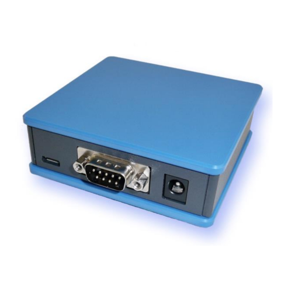
Page 9: Enclosure "4.0 Sky With D-Sub Connector
Jump to: Table of Content 3.4 E “4.0 S ” NCLOSURE WITH UB CONNECTOR Front with slot for USB stick. Matches are shown Reverse side shows D-Sub connector for data and just for size reference: barrel connector for power. The micro USB port is for configuration only: Optional, a DIN rail fitting is available: Page: 9... -
Page 10: Enclosure "4.0 Sky With Wago Connector
Jump to: Table of Content 3.5 E “4.0 S ” WAGO NCLOSURE WITH CONNECTOR Front with slot for USB stick. Matches are shown Reverse side shows the two WAGO connectors just for size reference: for data and power: Optional, a DIN rail fitting is available: WAGO connector are great with single wires. -
Page 11: Enclosure "4.0 Sky" With Ethernet And Wago Connector
Jump to: Table of Content 3.6 E “4.0 S ” WAGO NCLOSURE WITH THERNET AND CONNECTOR Front with slot for USB stick. Matches are shown Reverse side shows Ethernet (RJ45) and WAGO just for size reference: connector for data and power. The micro USB port is for configuration only: Optional, a DIN rail fitting is available: There is an optional adapter piece to connect the... -
Page 12: Enclosure "4.0 Silver" With Screw Type Connector
Jump to: Table of Content 3.7 E “4.0 S ” NCLOSURE ILVER WITH SCREW TYPE CONNECTOR View into the enclosure with the lid unscrewed. Optional, a DIN rail fitting is available: During normal operation, the enclosure is sealed. Page : 12 2022/04/11... -
Page 13: Usb Storage Stick
Companion Software” .. “USB Storage” ether in this document, or in the overall “User Manual Serie 4.0” document. Alternatively, third party tools for Windows can be used to format large USB sticks. Please note: Avisaro can not support those third party tools within our technical support via telephone or email. -
Page 14: Recommended Memory Sticks
Jump to: Table of Content The appropriate memory size also depends on the intended use. Due to the technology, memory sticks with an extremely high capacity are typically less robust than smaller memory sizes. The loggers have a "ring memory" that can be optionally activated. If the memory stick becomes full (approx. less than 100MB free memory) the oldest files are deleted - this is a useful setting for some applications. -
Page 15: Not Recommended
Jump to: Table of Content Innodisk USB Drive 3SE 4-32 GB Industrial SLC Technology 4.4.2 Not recommended Manufacturer Model Picture Capacity Technology Remarks Verbatim Slider 8 GB Consumer Stick failures after Store N Go short period of time Page: 15 2022/04/11... -
Page 16: Interface Description And Pin Layout
Heads-up: There are sometimes Micro USB cable which only do power supply, but not data. Those are used i.e. with mobile phones. If the Avisaro device is powered, but no data connection to the PC – just choose a different USB cable. -
Page 17: Power Supply
Jump to: Table of Content Configuration Power 5.3 P OWER UPPLY For regular operation, an external power supply must be connected. Powering the device through micro-USB is not (!) sufficient. 5.3.1 Barrel Connector Power supply at the “D-Sub” version is realized using a widely used barrel connector: The matching plug has the following dimensions (which are widely used and very much a ‘standard’): •... -
Page 18: Signal Levels
Supply voltage does not carry an output voltage – thus if the device is powered via barrel connector, Pin 9 does not show the input voltage (internal diode). This is for security reason. If needed, Avisaro can modify the device such that this pin can be used to power other devices. - Page 19 Jump to: Table of Content Connector Interface Signal Direction WAGO A RS232 VCC (6..32V) Power Power & Signal WAGO B RS232 VCC (6..32V) Power Power & Signal Cables are connected with the WAGO 734 series connectors. In most product configurations, those adapters are shipped with the box.
-
Page 20: Using The Wago Connector
9.5 mm. Polarity: middle pin is + voltage, outside is ground (-) voltage. Same voltage as described above. Please note: For the Avisaro 4.0 family with 2x RS232 WAGO: only one of those connectors fit – two connectors are to wide ! 5.4.7... -
Page 21: Rs485 Bus Interface
Jump to: Table of Content VCC (6..32V) Power n.c. n.c. 5.5 RS485 B NTERFACE This is an industry standard RS485 bus connection. 5.5.1 Default RS485 settings Those are the default settings: Baudrate 9600 No of bits Parity bits none Stop bits Flow control none 5.5.2... -
Page 22: Using The Wago Connector
Jump to: Table of Content Connector Interface Signal Direction WAGO A RS485 n.c. Not connected n.c. Not connected Signal B / D+ RS485 Bus Signal A / D- RS485 Bus VCC (6..32V) Power Power & Signal WAGO B RS485 n.c. Not connected n.c. -
Page 23: Can Interface
5.6.2 Storage format and network packaging Please check chapter “Avisaro Internal Data Formats” later in this document on how CAN messages are stored on USB memory or forwarded over the network. There are easy to read text formats as well as compact binary formats available. -
Page 24: Signal Levels
Jump to: Table of Content 5.6.3 Signal levels Voltage range on CAN-H / CAN-L: 4 - 16V Transceiver used: SN65HVD family by Texas Instruments. Other transceivers upon request 5.6.4 Terminating resistor Whether or not there is a 120 ohm terminating resistor depends on the product: Product No Name 120 Ohm Termination... -
Page 25: Wago - 2X Can Interface ("M43324" / "C43324")
Supply voltage does not carry an output voltage – thus if the device is powered via barrel connector, Pin 9 does not show the input voltage (internal diode). This is for security reason. If needed, Avisaro can modify the device such that this pin can be used to power other devices. -
Page 26: Using The Wago Connector
9.5 mm. Polarity: middle pin is + voltage, outside is ground (-) voltage. Same voltage as described above. Please note: For the Avisaro 4.0 family with 2x CAN WAGO: only one of those connectors fit – two connectors are to wide ! 5.6.9... -
Page 27: 5.6.10 M8 - 1X Can Interface
Jump to: Table of Content Connector Interface Signal Direction Screw Type Power & Signal VCC (6..32V) Power n.c. n.c. n.c. n.c. CAN-H CAN Bus CAN-L CAN Bus The 120 Ohm “Line Termination” resistor can be switched on/off via configuration. Thus, no DIP switch needs to be used. -
Page 28: 5.6.11 M12 (Male) - 1X Can Interface
Jump to: Table of Content Supply CAN-H 4 pol, female 5.6.11 M12 (male) - 1x CAN Interface Optional, a M12 male connector is available. Standard M12 connector (male) Connector Interface Signal Direction M12, CAN-H 5 pol, male CAN-L do not use Supply Power Supply Power Signal and Power Ground... -
Page 29: Ethernet (Rj45 Lan) Interface
Jump to: Table of Content 5.7 E (RJ45 LAN) I THERNET NTERFACE This is an industry standard Ethernet (LAN) interface. Supported rates are: • 10 BaseT • 100 BaseT The port does not (!) cross automatically. Thus, if connected directly to a PC, either the PC has to be auto-crossing or you need to use a Ethernet Cross-Over cable. -
Page 30: Wago - 4X Current Loop 4
Jump to: Table of Content 5.8.3 WAGO – 4x current loop 4..20mA (“M47724” / “C47724”) Please note: There was a firmware bug which resulted in switched polarity and incorrect readings. Make sure to update to a firmware larger to 2.65. Check chapter firmware update in this document for details. Connector Interface Signal... - Page 31 Jump to: Table of Content 1 2 3 4 5 6 7 8 Connector Interface Signal Direction Screw Type ADC3 & ADC4 Power & Signal 4..20mA VCC (6..32V) Power ADC4 - mA (-) ADC4 - mA (+) ADC3 - mA (-) ADC3 - mA (+) Future Use (not connected)
-
Page 32: Analog 0
Jump to: Table of Content 5.9 Analog 0..10V Interface The 0..10V interface can be used for “simple” single-ended voltage measurements, as well as demanding “differential” measurements. The measuring is isolated - thus it can be operated on a different ground reference than the power supply. -
Page 33: Wago - 4X 0
Jump to: Table of Content 5.9.4 WAGO - 4x 0..10V Interface (“M49924” / “C49924”) Connector Interface Signal Direction WAGO A & 2 0..10V (+) 0..10V 0..10V (-) 0..10V (+) 0..10V (-) not connected Signal GND Signal GND WAGO B & 4 0..10V (+) Page: 33 2022/04/11... - Page 34 Jump to: Table of Content 0..10V 0..10V (-) 0..10V (+) 0..10V (-) VCC (6..32V) Power Supply Power GND Cables are connected with the WAGO 734 series connectors. In most product configurations, those adapters are shipped with the box. Check the 'scope of delivery' list. Page : 34 2022/04/11...
-
Page 35: Configuration: 'Pc Companion Software
6.3 D ETAILED DOCUMENTATION This current document shows only selected parts of the full “Avisaro PC Companion Software” user manual. The motivation is to keep this document as compact as possible. Please find the extensive “Avisaro PC Companion Software” document in the support section of the... -
Page 36: Pc Companion Software" Installation
6.5 D RIVER INSTALLATION If you connect the Avisaro Device to the PC using a Micro USB cable, a virtual COM port driver is installed. If this driver does not install automatically, you can download and install this manually: http://www.avisaro.de/de/40-PC-Treiber.html (German site) http://www.avisaro.com/en/40-ENG-PC-Driver.html... -
Page 37: Initial Set-Up
SING THE OMPANION Click on “Write Config” to transmit changes in the PC tool to the Avisaro device. Click on “Read Config” to display the currently stored values (if you navigate between options, the latest settings are read of course automatically). -
Page 38: Firmware And Configuration Update
7.1.1 Introduction The configuration of the Avisaro 4.0 defines how the devices behave. Settings like baudrate, time&date, Internet access parameter, etc. are variable and can be defined by the user. There are two ways to configure the Avisaro 4.0 devices: 1) Connect the device to a PC using a Micro-USB cable. -
Page 39: Firmware Update
There are three ways to update the firmware of the Avisaro 4.0 family: 1. Via USB Stick If the Avisaro 4.0 product has a USB Host port, a new firmware can be uploaded using a USB stick. See details below. -
Page 40: Via Usb Stick
7.2.4 Via FTP server / internet Avisaro Devices can be update remotely. This is a powerful service feature. To enable, navigate to “Data Endpoints”->“CLoud setting” and activate “Remote firmware update”. Please refer to the document “PC Companion” for details, chapter “Data Endpoints-> Cloud Settings”. - Page 41 30 seconds which is sensitive to power failure) Recommendations: • It is highly recommended to create a different user pointing to a different subdirectory for each Avisaro Data logger. This way, a firmware update can be directed to each Page: 41 2022/04/11...
-
Page 42: Avisaro Internal Data Formats
Jump to: Table of Content VISARO INTERNAL DATA FORMATS 8.1 CAN – CSV T EXT FORMAT This is the default format for CAN recording into a file. The format is 8.1.1 CAN CSV text description File name depends on configuration (every day a new file or every hour), i.e. “181102.txt”: Format: Date, Time, Millisecond, CAN Bus Nr., CAN ID, Message length, Data 2018/11/02,15:06:27,480, $C2, 0fffffff, 8, 00, 00, 00, 00, 00, 00, 00, 00 2018/11/02,15:06:28,512, $C2, 0fffffff, 8, 00, 00, 00, 00, 00, 00, 00, 00... -
Page 43: Can - Binary Data Format
Jump to: Table of Content 8466.949000 1 d 8 00 00 00 00 00 00 00 00 8467.133000 1 d 8 00 00 00 00 00 00 00 00 8467.269000 1 d 8 00 00 00 00 00 00 00 00 8467.591000 2 d 8 01 23 45 06 00 00 00 00 8467.710000 2... -
Page 44: Packaging
Jump to: Table of Content 23..16 31..23 7…0 Millisecond time stamp. Value in ms since module power on. 15...8 23..16 31..23 8.3.2 Packaging Multiple CAN frame container could be packed into one UDP or TCP packet. It is ensured that always a complete CAN container is packed. -
Page 45: Declarations
Jump to: Table of Content ECLARATIONS 9.1 EC/EU D ECLARATION OF ONFORMITY Page: 45 2022/04/11... -
Page 46: Contact And Support
Jump to: Table of Content 10 C ONTACT AND UPPORT Please contact Avisaro if there are any questions: Avisaro AG Grosser Kolonnenweg 18 E 30163 Hannover Germany Email: support@avisaro.com End of this documentation Page : 46 2022/04/11...
Need help?
Do you have a question about the 4.0 Series and is the answer not in the manual?
Questions and answers