Table of Contents
Advertisement
Quick Links
Advertisement
Table of Contents

Related Manuals for MFJ MFJ-249C


Summary of Contents for MFJ MFJ-249C
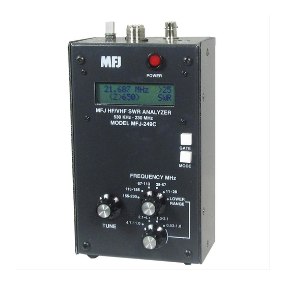
- Page 1 Model MFJ-249C INSTRUCTION MANUAL CAUTION: Read All Instructions Before Operating Equipment MFJ ENTERPRISES, INC. 300 Industrial Park Road Starkville, MS 39759 USA Tel: 662-323-5869 Fax: 662-323-6551 COPYRIGHT 2014 MFJ ENTERPRISES, INC. VERSION 1A...
-
Page 2: Table Of Contents
MFJ-249C Instruction Manual HF/VHF SWR Analyzer TABLE OF CONTENTS 1.0 INTRODUCTION..............................1 A Quick Word about Accuracy......................1 Typical Uses ............................2 Frequency Range ..........................2 2.0 POWER SOURCES .............................. 2 External Power Supply ........................2 Using Internal Batteries ........................3 Using Rechargeable “AA”... -
Page 3: Introduction
However, the MFJ-249C minimizes this problem with careful pc layout and by using low-capacitance microwave-grade surface-mount components with virtually no lead length. -
Page 4: Typical Uses
-25 dBc (dB below the fundamental-frequency carrier). The internal source impedance (Zo) is 50 ohms. A more complete description of the MFJ-249C's features along with proper measurement methods can be found by reading sections covering the particular measurement you wish to make. Consult the table of contents for various applications. -
Page 5: Using Internal Batteries
2.1 mm The MFJ-249C has a recessed 2.1 mm power jack located on the top-right-hand side of the unit. It is labeled Power 13.8 VDC. The jack's outside barrel contact is negative and the center pin is positive. Inserting a power plug into the power jack automatically disables the internal batteries as a power source. -
Page 6: Power Saving" Mode (Sleep Mode)
IMPORTANT WARNING: Never Apply RF or any other external voltage to the Antenna port of this unit. The MFJ-249C uses zero bias detector diodes that may be damaged by external voltages. Read Section-2.0 before applying power! Incorrect supply voltages will also damage this unit. -
Page 7: Main Mode Descriptions
Section 3.2 (SWR, Impedance R&X). The MFJ-249C has three (3) Basic Operating Modes that are used for conducting a variety of measurements. If you tap (momentarily press) the Mode button, the analyzer steps to the next Mode selection. The three main modes and their opening screens are described in Section-3.3 below:... -
Page 8: Blinking "Voltage Low" Display Warning
A basic understanding of antenna theory and transmission line behavior will be helpful for making the best use of the data provided by your MFJ-249C. The ARRL Handbook and ARRL Antenna Book provide concise peer- reviewed explanations that should suffice for most applications. When it comes to the finer points of antenna design, there is (unfortunately) a fair amount of mis-information circulating on the web and over the airwaves. -
Page 9: Adjusting Simple Antennas
MFJ-249C Instruction Manual HF/VHF SWR Analyzer 3.) Always use good quality 50-ohm cable and connectors when making SWR measurements. Contaminated, mismatched, or damaged cable will introduce significant error. ADJUSTING SIMPLE ANTENNAS Most antennas are tuned for operating frequency by varying the element length -- and most homemade verticals and dipoles are very simple to adjust. -
Page 10: Testing And Tuning Stubs And Transmission Lines
( like 1, 1-1/2, etc.). Connect the PL-259 to the "ANTENNA" connector of the MFJ-249C and adjust the line or stub by the following method. For critical stubs you may want to gradually trim the stub to frequency. -
Page 11: Impedance Of Transmission Lines Or Beverage Antennas
Impedance of Transmission Lines or Beverage antennas The impedance of transmission lines between 15 and 150 ohms can be measured with the MFJ- 249C, a 250 ohm potentiometer, and an ohm meter. Lines of higher impedance can be measured with a higher resistance potentiometer if a broad band transformer is used (see the section on testing transformers) to transform the line impedance to approximately 50 ohms. -
Page 12: Testing Rf Transformers
The 50 ohm winding is connected through a short 50 ohm cable to the "ANTENNA" connector on the MFJ-249C. The other winding(s) of the transformer is then terminated with a low inductance resistor that is equal to the windings impedance. The MFJ-249C can then be swept through the desired transformer frequency range. -
Page 13: Measure Capacitance
F = MHz C = pF Resonant Frequency of Tuned Circuits The MFJ-249C can be used to measure the resonant frequency of tuned circuits by two methods. The first method involves placing a 50 ohm resistor in series with the MFJ-249C "ANTENNA" connector. -
Page 14: Testing Rf Chokes
TECHNICAL ASSISTANCE If you have any problem with your MFJ-249C, first check the appropriate section of this manual. If the manual does not reference your problem and the problem isn't solved by reading the manual, you may call MFJ Technical Service at 662-323-0549 or the MFJ Factory at 622-323-5869. - Page 15 MFJ Enterprises, Inc. warrants to the original owner of this product, if manufactured by MFJ Enterprises, Inc. and purchased from an authorized dealer or directly from MFJ Enterprises, Inc. to be free from defects in material and workmanship for a period of 12 months from date of purchase provided the following terms of this warranty are satisfied.
- Page 16 MFJ-249C Manual Version 1A 300 Industrial Park Road Printed In U.S.A. Starkville, MS 39759...
Need help?
Do you have a question about the MFJ-249C and is the answer not in the manual?
Questions and answers