Table of Contents
Advertisement
Available languages
Available languages
Quick Links
Item #1004 101 742, 1004 101 731
Model #5348WWHD, 5348GYHD
USE AND CARE GUIDE
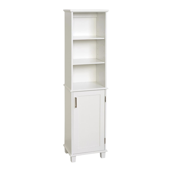
LINEN TOWER
Questions, problems, missing parts?
Before returning to the store, call Glacier Bay Customer Service
8 a.m. - 7 p.m., EST, Monday - Friday, 9 a.m. - 6 p.m., EST, Saturday
1-855-HD-GLACIER
HOMEDEPOT.COM/GLACIERBAY
THANK YOU
We appreciate the trust and confidence you have placed in Glacier Bay through the purchase of this linen tower.
We strive to continually create quality products designed to enhance your home. Visit us online to see our full line of products
available for your home improvement needs. Thank you for choosing Glacier Bay!
Advertisement
Chapters
Table of Contents

Related Manuals for Glacier bay 5348WWHD


Summary of Contents for Glacier bay 5348WWHD
- Page 1 THANK YOU We appreciate the trust and confidence you have placed in Glacier Bay through the purchase of this linen tower. We strive to continually create quality products designed to enhance your home. Visit us online to see our full line of products...
-
Page 2: Table Of Contents
Glacier Bay products are manufactured with superior quality standards and workmanship and are backed by our limited lifetime warranty. Glacier Bay products are warranted to the original consumer purchaser to be free of defects in materials or workmanship. We will replace FREE OF CHARGE any product or parts that proves defective. -
Page 3: Pre-Assembly
Pre-Assembly PLANNING ASSEMBLY □ Identify all parts and hardware pieces before you begin. □ When laying out parts, place them on a soft surface to prevent scratching. TOOLS REQUIRED Phillips Hammer Pencil Drill screwdriver HARDWARE INCLUDED NOTE: Hardware not shown to actual size. Some of the hardware offered may be more than needed, please keep them as spare parts. - Page 4 [Heading goes here] Pre-Assembly (continued) HARDWARE INCLUDED (continued) NOTE: Hardware not shown to actual size. Some of the hardware offered may be more than needed, please keep them as spare parts. Door handle Door handle screw Hinge Hinge screw Magnet Magnet screw Magnet strike Magnet strike screw...
- Page 5 [Heading goes here] Pre-Assembly (continued) HARDWARE INCLUDED (continued) NOTE: Hardware not shown to actual size. Some of the hardware offered may be more than needed, please keep them as spare parts. Cam cover x 12 Mounting screw Wall anchor Spacer Washer Nail x 16...
-
Page 6: Package Contents
Pre-Assembly (continued) PACKAGE CONTENTS Top Panel Top Left Side Panel Top Right Side Panel Fixed Shelf Bottom Left Side Panel Bottom Right Side Panel Bottom Panel Hanging Rail Door Foot Back Panel Adjustable Shelf... -
Page 7: Assembly
Assembly (continued) Attaching the hinges arrow direction □ Attach the hinges (II) to the bottom right side panel (F) using the hinge screws (JJ). □ Attach the magnet (KK) to the bottom left side panel (E) using the magnet screws (LL). □... - Page 8 Assembly (continued) Inserting cams into the hanging rails □ Insert cams (BB) into the hanging rails (H) and note the direction of the arrow on the cams (BB), as shown. arrow direction arrow direction...
- Page 9 Assembly (continued) Attaching the bottom panel □ Insert the short dowels (CC) into the hanging rail (H) and attach to the side panels (E and F). □ Insert short dowels (CC) into the side panels (E and F) and then attach the bottom panel (G) to the side panels (E and F) using the wood screws (EE), as shown.
- Page 10 [Heading goes here] Assembly (continued) Attaching the feet □ Using the hex wrench (V V ), attach the feet (J) to the bottom panel (G) using the foot screws (FF), as shown. Do not overtighten the foot screws (FF).
- Page 11 [Heading goes here] Assembly (continued) Inserting cams into the top side panels □ Attach the cam bolts (AA) to the side panels (B and C). arrow direction □ Insert cams (BB) to the side panels (B and C) and note the direction of the arrow on the cams (BB), as shown.
- Page 12 [Heading goes here] Assembly (continued) Attaching cam bolts to the fixed shelf □ Attach the cam bolts (AA) to the fixed shelf (D), as shown.
- Page 13 [Heading goes here] Assembly (continued) Attaching the fixed shelf □ Insert the short dowels (CC) into the hanging rail (H) and attach to the side panels (B and C). □ Insert the long dowels (DD) into the side panels (B and C). □...
- Page 14 [Heading goes here] Assembly (continued) Attaching cam bolts to the top panel □ Attach the cam bolts (AA) to the top panel (A), as shown.
- Page 15 [Heading goes here] Assembly (continued) Attaching the top panel □ Insert short dowels (CC) into the top side panels (B and C). □ Attach the top panel (A) to the side panels (B and C), as shown. □ Tighten the cams (BB) by turning them clockwise until snug, do not overtighten cams (BB).
- Page 16 [Heading goes here] Assembly (continued) Attaching the bottom side panels to the fixed self □ Attach the bottom side panels (E and F) to the fixed shelf (D) and tighten the cams (BB) by turning them clockwise until snug, do not overtighten cams (BB), as shown.
- Page 17 [Heading goes here] Assembly (continued) Attaching the door handle □ Attach the door handle (GG) to the door (I) using the door handle screws (HH). □ Make sure the raised dimples on the magnet strike (MM) are facing the door (I) and attach using the magnet strike screw (NN), as shown.
- Page 18 [Heading goes here] Assembly (continued) Attaching the door to the assembly □ Attach the door (I) using the hinge screws (JJ), as shown.
- Page 19 [Heading goes here] Assembly (continued) Adjusting the door □ To make horizontal adjustments see figure 1. □ To make vertical adjustments see figure 2. figure 1 (horizontal adjustment) hinge door figure 2 (vertical adjustment) door hinge HOMEDEPOT.COM/GLACIERBAY Please contact 1-855-HD-GLACIER for further assistance.
- Page 20 [Heading goes here] Assembly (continued) Attaching the back panel □ Attach the back panel (K) to the assembly using the nails (UU).
-
Page 21: Installation
[Heading goes here] Installation Attaching the unit to the wall NOTE: It is imperative that the unit be fastened to the wall for safety reasons. NOTE: Before cutting, drilling, or hammering into any wall surface, verify the location of electrical, plumbing, and gas lines. -
Page 22: Care & Cleaning
[Heading goes here] Assembly (continued) Inserting adjustable shelves □ Insert the adjustable shelves (L), using the shelf pins (OO). □ Use the cam covers (PP) to cover all cams (BB). cam covers (PP) Care and Cleaning □ Cleaning with a dry cloth may be sufficient. □... - Page 23 Questions, problems, missing parts? Before returning to the store, call Glacier Bay Customer Service 8 a.m. - 7 p.m., EST, Monday - Friday, 9 a.m. - 6 p.m., EST, Saturday 1-855-HD-GLACIER HOMEDEPOT.COM/GLACIERBAY Retain this manual for future use. IS5348-I...
- Page 24 GRACIAS Agradecemos la confianza que ha depositado en Glacier Bay a través de la adquisición de esta torre para ropa blanca. Nos esforzamos constantemente en crear productos de calidad diseñados para embellecer su hogar. Visítenos en línea y vea nuestra línea completa de productos...
- Page 25 Los productos Glacier Bay están fabricados con normas y manufactura de calidad superior y están respaldados por nuestra garantía limitada de por vida. Los productos Glacier Bay garantizan al comprador consumidor original que están libres de defectos en materiales o manufactura.
-
Page 26: Antes Del Ensamble
Antes del ensamble PLANIFICACIÓN DEL ENSAMBLE □ Identifique todas las piezas y las piezas de tornillería antes de comenzar. □ Al esparcir las partes, colóquelas sobre una superficie suave para evitar que se rayen. HERRAMIENTAS NECESARIAS Destornillador Martillo Lápiz Taladro Phillips ELEMENTOS INCLUIDOS NOTA: La tornillería no se ilustra en su tamaño real. - Page 27 [Heading goes here] Antes del ensamble (continuado) ELEMENTOS INCLUIDOS ( continuación ) NOTA: La tornillería no se ilustra en su tamaño real. Es posible que se provean más piezas de tornillería que las que se requieren, por favor consérvelas como piezas de repuesto.
- Page 28 [Heading goes here] Antes del ensamble (continuado) ELEMENTOS INCLUIDOS ( continuación ) NOTA: La tornillería no se ilustra en su tamaño real. Es posible que se provean más piezas de tornillería que las que se requieren, por favor consérvelas como piezas de repuesto.
-
Page 29: Contenido Del Paquete
Antes del ensamble (continuado) CONTENIDO DEL PAQUETE Panel superior Panel lateral superior izquierdo Panel lateral superior derecho Repisa fija Panel lateral inferior izquierdo Panel lateral inferior derecho Panel inferior Riel colgante Puerta Pata Panel posterior Repisa regulable... -
Page 30: Ensamble
Ensamble (continuado) Fijación de las bisagras dirección de flecha □ Fije las bisagras (II) al panel lateral derecho inferior (F) usando los tornillos para bisagra (JJ). □ Fije el imán (KK) al panel lateral inferior izquierdo (E) usando los tornillos para imán (LL). □... - Page 31 Ensamble (continuado) Inserción de levas dentro de los rieles colgantes □ Inserte las levas (BB) dentro de los rieles colgantes (H) y tenga en cuenta la dirección de la flecha en las levas (BB), como se ilustra. dirección de flecha dirección de flecha...
- Page 32 Ensamble (continuado) Fijación del panel inferior □ Inserte tas clavijas cortas (CC) dentro del riel colgante (H) y fíjelo a los paneles laterales (E y F). □ Inserte tas clavijas cortas (CC) dentro de los paneles laterales (E y F) y luego fije el panel inferior (G) a los paneles laterales (E y F) usando los tornillos para madera (EE), como se ilustra.
- Page 33 [Heading goes here] Ensamble (continuado) Fijación de las patas □ Usando la llave Allen hexagonal (VV), fije las patas (I) al panel inferior (G) usando los tornillos para patas (FF), como se ilustra. No ajuste los tornillos de patas de más (FF).
- Page 34 [Heading goes here] Ensamble (continuado) Inserción de levas dentro de los paneles laterales superiores dirección de flecha □ Fije los pernos de leva (AA) a los paneles laterales (B y C). □ Inserte las levas (BB) en los paneles laterales (C y D), y tenga en cuenta la dirección de la flecha en las levas (BB), como se ilustra.
- Page 35 [Heading goes here] Ensamble (continuado) Fijación de los pernos de leva a la repisa fija □ Fije los pernos de leva (AA) a la repisa fija (D), como se ilustra.
- Page 36 [Heading goes here] Ensamble (continuado) Fijación de la repisa fija □ Inserte las clavijas cortas (CC) dentro del riel colgante (H) y fíjelo a los paneles laterales (B y C). □ Inserte las clavijas largas (DD) dentro de los paneles laterales (B y C).
- Page 37 [Heading goes here] Ensamble (continuado) Fijación de los pernos de leva al panel superior □ Fije los pernos de leva (AA) al panel superior (A), como se ilustra.
- Page 38 [Heading goes here] Ensamble (continuado) Fijación del panel superior □ Inserte las clavijas cortas (CC) dentro de los paneles laterales superiores (B y C). □ Fije el panel superior (A) a los paneles laterales (B y C), como se ilustra. □...
- Page 39 [Heading goes here] Ensamble (continuado) Fijación de los paneles laterales inferiores a la repisa fija □ Fije los paneles laterales inferiores (E y F) a la repisa fija (D) y ajuste las levas (BB) girándolas en el sentido de las agujas del reloj hasta que estén bien ajustadas;...
- Page 40 [Heading goes here] Ensamble (continuado) Fijación de la manija de puerta □ Fije la manija de puerta (GG) a la puerta (I) usando los tornillos para manija de puerta (HH). □ Asegúrese de que las depresiones con relieve sobre la contrachapa de imán (MM) estén orientadas hacia la puerta (I) y realice la fijación con el tornillo para contrachapa de imán (NN), como se ilustra.
- Page 41 [Heading goes here] Ensamble (continuado) Fijación de la puerta al conjunto □ Fije la puerta (I) usando los tornillos para bisagra (JJ), como se ilustra.
- Page 42 [Heading goes here] Ensamble (continuado) Ajuste de la puerta □ Consulte la figura 1 para realizar ajustes horizontales. □ Consulte la figura 2 para realizar ajustes verticales. figura 1 (ajuste horizontal) bisagra puerta figura 2 (ajuste vertical) puerta bisagra HOMEDEPOT.COM /GLACIERBAY Contáctese con 1-855-HD-GLACIER para recibir ayuda adicional.
- Page 43 [Heading goes here] Ensamble (continuado) Fijación del panel posterior □ Fije el panel posterior (K) al conjunto usando los clavos (UU).
-
Page 44: Instalación
[Heading goes here] Instalación Montaje de la unidad a la pared NOTA: Por razones de seguridad, es fundamental que esta unidad sea montada a la pared. NOTA: Antes de cortar, taladrar o martillar cualquier superficie de pared, verifique la ubicación de los conductos eléctricos y las tuberías de agua y gas. -
Page 45: Cuidado Y Limpieza
[Heading goes here] Ensamble (continuado) Inserción de las repisas regulables □ Inserte las repisas regulables (L), usando los soportes de repisa (OO). □ Use las tapas de levas (PP) para tapar todas las levas (BB). tapas de levas (PP) Cuidado y limpieza □... - Page 46 ¿Tiene preguntas, problemas, le faltan piezas? Antes de regresar a la tienda, llame al Servicio al Cliente de Glacier Bay 8 a.m. - 7 p.m., Hora Estándar del Este, de lunes a viernes, de 9 a.m. - 6 p.m., Hora Estándar del Este, sábado 1-855-HD-GLACIER HOMEDEPOT.COM/GLACIERBAY...
Need help?
Do you have a question about the 5348WWHD and is the answer not in the manual?
Questions and answers