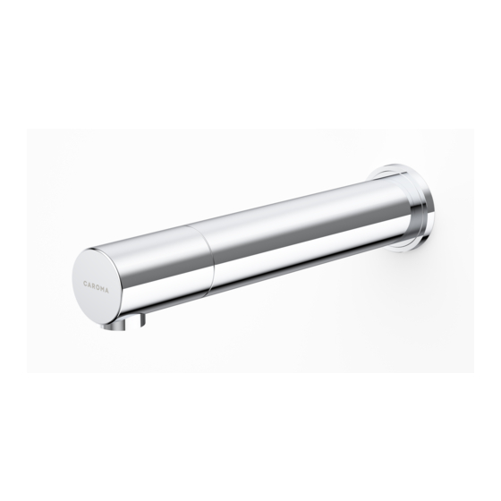
Caroma G Series Installation And Maintenance Manual
Hide thumbs
Also See for G Series:
- Installation and maintenance instructions manual (16 pages) ,
- Installation and maintenance instructions manual (16 pages) ,
- Installation and maintenance manual (16 pages)
Table of Contents

Summary of Contents for Caroma G Series
- Page 1 H A N D S F R E E W A L L M O U N T E D H A N D S F R E E W A L L M O U N T E D G SERIES ELECTRONIC OUTLET 205...
- Page 2 The tradenames, trademarks, logos and service marks presented in this document, including their design, are the property of Caroma Industries LTD or other third parties and you are not permitted to use them without the prior written consent of Caroma Industries LTD or such third party as may own them.
-
Page 3: Technical Data
Flow will automatically stop after continuous running of 90 seconds (Can Security time: be reduced with optional remote control) Max. 70°C (To prevent scalding, ensure water is tempered to the Hot water temperature: appropriate temperature for the specific bathroom requirements) Spare parts can be downloaded from specify.caroma.com.au... -
Page 4: Pack Contents
PACK CONTENTS 1 x Spout and attachments (incl. electronic unit) 1 x Wall rosette 1 x Tubular base 1 X Corrugated Tube 1 X M4X6 screw 1 x Dual power input box with inlet nipple and filter 9V transformer OPERATION - This outlet features an IP67 dual power input box. The product can be operated with a 9V battery or a 9V transformer. -
Page 5: Pre-Installation Info
PRE-INSTALLATION INFO CHECK CONTENTS Separate all parts from the packaging and check each part with the pack contents section. Pay attention to the variations of the different models. Make sure all parts are accounted for before discarding any packaging material. If any parts are missing, do not attempt to install your electronic outlet until you obtain the missing parts. -
Page 6: Installation
INSTALLATION INSTALLING THE OUTLET Shut off the water supply. Cut an adequate opening in the wall for the dimensions of the product base, and the corrugated tube. Dismantle the outlet base. Drill four small holes for the product base support and drive the anchors in. - Page 7 INSTALLATION Mount the product base to the opening cut in the wall, and secure the base support to the four small holes using 4 screws. Make sure that the base is leveled to the centre. Ensure the outlet base is perpendicular to the wall so the spout will be appropriately positioned for use.
- Page 8 INSTALLATION Cut the temporary outlet base cover. Once the works on electricity, plumbing and tiles have been finished, assemble the wall rosette through the outlet base. Carefully tie the flexible leads (power and sensor) with string to the water tube and feed it through the corrugated tubing.
- Page 9 INSTALLATION CONNECTING THE WATER SUPPLY IMPORTANT: Product was supplied with a self adjusting sensor. The ideal sensor range for the specific location will be set automatically. OBJECT Now, remove the protective sticker Before proceeding, check that no objects are in front of the sensor besides the washbasin.
- Page 10 REMOTE CONTROL FUNCTIONS (OPTIONAL) DETECTION RANGE DELAY OUT TIME DELAY IN TIME TEMPORARY OFF FUNCTION SECURITY TIME SELF ADJUSTMENT MODE COMFORT FLUSH RESET HYGIENE FLUSH ADJUSTING THE SETTINGS WITH THE REMOTE CONTROL If necessary, the sensor settings can be adjusted as following: Shut off the water supply. In order to adjust the sensor with the remote control, hold the remote control straight in front of the sensor in a distance of about (15- 20cm).
-
Page 11: Settings Adjustment
SETTINGS ADJUSTMENT DETECTION RANGE: This outlet was supplied with a self adjusting sensor. The ideal detection range for the specific location will be set automatically. Only if necessary, use the remote control to adjust the sensor range as follows: Press the RANGE button. - Page 12 SETTINGS ADJUSTMENT DELAY OUT TIME: This button allows modifying the water flow time after the user removes his hands from the outlet. A delay out time close to 0 will save more water. An increased delay out time will make the user experience more comfortable. If required, the delay out time can be modified as follows: Press the OUT button.
-
Page 13: Battery Replacement
BATTERY REPLACEMENT Carefully open the dual power input box, using the Allen key provided. Remove the old battery and replace it with a new 9V battery (Lithium battery is recommended). Close the box. IMPORTANT: These models were supplied with a self adjusting sensor. The ideal sensor range for the specific location will be set automatically again after changing the battery. -
Page 14: Maintenance
MAINTENANCE FILTER CLEANING INSTRUCTIONS These models are provided with a stainless steel filter preventing foreign particles to enter the lines. It is recommended to clean the filter every six (6) month. If the water flow has decreased, this may be because the filter is clogged. -
Page 15: Limited Warranty
LIMITED WARRANTY Please refer to www.caroma.com.au for details on warranty of this product. If you have any other questions do not hesitate to contact customer service on 13 14 16. Please note, warranty does not cover product damage caused by the following: - Incorrect installation. -
Page 16: Troubleshooting
TROUBLESHOOTING PROBLEM INDICATOR CAUSE SOLUTION No water 1.Sensor flashes coming out continuously when of the outlet: user’s hands are Low battery. Replace battery within the sensor’s range. 2. LED in the sen- 1. Range is too short. Increase the range sor does not flash once when user’s 2.


Need help?
Do you have a question about the G Series and is the answer not in the manual?
Questions and answers