Table of Contents
Advertisement
Advertisement
Table of Contents

Subscribe to Our Youtube Channel
Related Manuals for Caroma Smart Command Eco Valve


Summary of Contents for Caroma Smart Command Eco Valve
-
Page 2: Table Of Contents
Contents Contents General ........................3 Indications regarding the instructions for use ................Symbols used ..........................Copyright / Standards / Warranty ....................Safety ........................5 Intended use ..........................Fundamental hazards ........................Hazards due to electric energy ....................... Maintenance and repair work ......................Installation instructions ....................6 Design and function ....................7 Scope of supply .......................... -
Page 3: General
1.1 Indications regarding the instructions for use These instructions will help you operate your Caroma Eco Valve in a safe and efficient manner. They form part of the scope of supply and have to be readily available at all times. -
Page 4: Copyright / Standards / Warranty
• Repair or conversion work performed by unauthorised persons, • Use of non-original Caroma accessories or spare parts. • Faulty parts that are not repaired immediately so as to limit the extent of damage as far as possible and not to have a negative effect on the safety of the device (repair obligation). -
Page 5: Safety
Due to the nature of the system, there cannot be a 100% guarantee that no water damage will occur. The Caroma Eco Valve is intended for use in cold water systems. Any other use or use beyond the intended use is considered unintended use. -
Page 6: Maintenance And Repair Work
(e.g. pieces of furniture), radio reception may be impaired or interrupted. Possibly, an additional Gateway will have to be installed to increase the range of the radio signal. The Caroma Eco Valve must be installed in frost-proof, non-condensing rooms. The Caroma Eco Valve must NOT be installed in inaccessible ducts. -
Page 7: Design And Function
4. Design and function 4. Design and function 4.1 Scope of supply 4.1 Scope of supply Legend Valve unit 9V battery (included) Emergency unlocking key Mains power supply Pipe adapters (2x) Commissioning, operation and maintenance manual... -
Page 8: Design
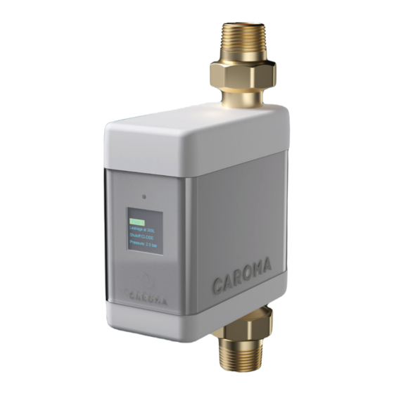
4.3 Function The Smart Command Eco Valve is an efficient leakage protection system. Thanks to permanent monitoring, any leak is detected at an early stage and the risk of extensive water damage is reduced because the water supply is cut off automatically. -
Page 9: Transport And Storage
5. Transport and storage 5. Transport and storage 5.1 Transport 5.1 Transport The device is completely assembled when delivered. It weighs approximately 1.3 kg. Attention! Improper transport may damage the device! The packaging serves as protection during transport. • Do not install the device if the packaging is severely damaged. •... -
Page 10: Installation And Commissioning
6.1 Safety instructions for installation and commissioning 6.1 Safety instructions for installation and commissioning Only authorized, qualified and specially trained Caroma personnel with the appropriate expertise shall install and commission the Caroma Eco Valve. Observe the general safety instructions for drinking water installations, such as the following: •... -
Page 11: Installation
6. Installation and commissioning 6. Installation and commissioning 6.2 Installation 6.2 Installation • Turn off the water supply prior to starting the installation work. Mount the device only in drinking water installations according to AS/NZS3500.1 and AS/NZS3500.4, directly downstream of the water metering device. Do not apply stresses. Flush the pipes before installation. - Page 12 6. Installation and commissioning 6. Installation and commissioning • Insert the battery. • Plug in the mains adapter to ensure power supply. The device is now ready to use! Operation and Maintenance Smart Command Intelligent Eco Valve...
-
Page 13: Operation And Settings
7.1. Operation and settings via the Smart Command App It’s easy to set your Smart Command Eco Valve via the Caroma Smart Command App on your smartphone or tablet. Simply install the current Caroma Smart Command App on your smartphone or tablet. - Page 14 7. Operation and settings 7.1.1. Settings range 7.1.1. Settings range Please find below important terms for the settings of the Smart Command Eco Valve in the Smart Command App. Examples are given for illustration. Explanation and setting options Default setting Volume-based leakage Maximum amount of water drawn after opening a draw-off point.
- Page 15 The warning sound can be switched on or off. Self-learning phase During the self-learning phase, the Caroma Eco Valve analyses water consumption and the typical usage. The measured values can then be used for your own, selected profile. The duration of the self-learning phase can range between one and 28 days.
-
Page 16: Displays And Actions Directly On The Device
7. Operation and settings 7. Operation and settings 7.2. Displays and actions directly on the device 7.2. Displays and actions directly on the device The user interface of the Eco Valve includes a 4-line LCD display, one LED for the status indicator and one touch switch. - Page 17 8. Emergency unlocking function 8. Emergency unlocking function 8.1 Emergency unlocking function 8.1 Emergency unlocking function The Eco Valve can be manually unlocked, for instance in case of loss of energy supply due to power failure or a missing or spent battery. The access to the emergency unlocking function is underneath the control unit.
-
Page 18: Emergency Unlocking Function
8. Emergency unlocking function 8. Emergency unlocking function • Remove the emergency unlocking key (A), the battery (B), and the battery compartment (C) • Pull the casing upwards and tip it sideways. Operation and Maintenance Smart Command Intelligent Eco Valve... - Page 19 8. Emergency unlocking function 8. Emergency unlocking function • Remove the wire clamp that connects the body of the Eco Valve with the motor unit and place the motor unit next to it, sideways (without removing the cables), thus opening access to the shut-off valve. Note: Electronics not shown •...
- Page 20 8. Emergency unlocking function 8. Emergency unlocking function Once you have drawn water, turn the shut-off valve by using the key until it is closed again and the water • ceases to flow. Re-assemble the device in reverse order. Operation and Maintenance Smart Command Intelligent Eco Valve...
-
Page 21: Components And Spare Parts
9. Spare Parts 9. Spare Parts Cover Battery compartment Shell Motor unit Pressure sensor Conductivity cartridge Inlet strainer Components and spare parts Power supply (no illustration) 510010 Pressure sensor with cable 510012 Conductivity cartridge 510013 Reed switch (no illustration) 510014 Inlet strainer, complete 510015 Temperature sensor (no illustration) -
Page 22: Maintenance
Completely remove the screw connections on the casing, remove the Eco Valve, check the inlet strainer, if required, remove it and rinse with clear water (replace if necessary). Re-assemble in reverse order. Slowly re-open water supply. We recommend annual servicing intervals with our Caroma service technicians or a certified specialist. Attention! Potential material damage due to improper care! •... -
Page 23: Faults
No turbine impulses have been registered over an Open a draw-off point and check Flow sens or extended period of time. Maybe the turbine or the whether the control displays any sensor is contaminated or defective. (LED) turbine impulses. Contact Attention: Limited leakage protection! Caroma service. - Page 24 11. Faults Alarm text Cause Correction Fault The pressure sensor does not pass on any Please contact Caroma service. Pressure sensor information, maybe due to a defect. Fault The temperature sensor does not pass on any Please contact Caroma service.
-
Page 25: Specifications
12. Specifications 12. Specifications Caroma Eco Valve Caroma Eco Valve Unit Value Battery 1 x 9V Block (6LR61) Buffer battery (on circuit board) 1 x CR 2032 IP Code IPX3 Standard wireless protocol Bluetooth ® Max. operating pressure 1400 Max. ambient air temperature °C... -
Page 26: Dimensions
13. Dimensions 13. Dimensions Nominal size DN 20 DN 25 DN 32 ¾“ 1“ 1¼“ 118.8 mm 118.8 mm 118.8 mm 39 mm 39 mm 39 mm 265.2 mm 261.2 mm 285.2 mm 191.2 mm 191.2 mm 191.2 mm 79.5 mm 79.5 mm 79.5 mm Operation and Maintenance Smart Command Intelligent Eco Valve...
Need help?
Do you have a question about the Smart Command Eco Valve and is the answer not in the manual?
Questions and answers