Caroma G Series Installation And Maintenance Manual
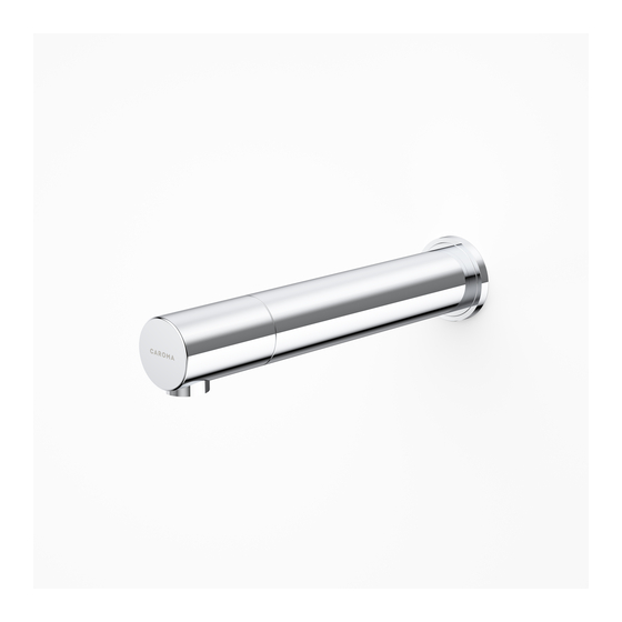
Electronic soap dispenser
Hide thumbs
Also See for G Series:
- Installation and maintenance instructions manual (16 pages) ,
- Installation and maintenance instructions manual (16 pages) ,
- Installation and maintenance manual (17 pages)
Table of Contents

Related Manuals for Caroma G Series


Summary of Contents for Caroma G Series
- Page 1 H A N D S F R E E W A L L M O U N T E D H A N D S F R E E W A L L M O U N T E D G SERIES ELECTRONIC...
- Page 2 The tradenames, trademarks, logos and service marks presented in this document, including their design, are the property of Caroma Industries LTD or other third parties and you are not permitted to use them without the prior written consent of Caroma Industries LTD or such third party as may own them.
-
Page 3: Technical Data
12V transformer (Optional battery box available, refer to spare parts online) Soap viscosity 100 – 3800 cc, Adjustable Standard discharge 35-155 mm +/- 10 mm Sensor range (customizable by optional remote control) Preset sensor range 80 mm +/- 10 mm Spare parts and accessories can be downloaded from specify.caroma.com.au... -
Page 4: Pre-Installation Info
Caroma liquid soap dispensers are suitable for use with any generic liquid soap of the correct viscosity and pH. The pH level of all soap used in Caroma liquid soap dispensers should be between 6.5 to 8.5. Lower levels will cause corrosion to the metal dispenser and even the rubber and plastic components. -
Page 5: Pack Contents
PACK CONTENTS 1 X BODY ASSEMBLY 1 X SOAP TANK WITH BOTTLE SUPPORT AND PUMP ASSEMBLY 1 X QUICK CONNECTION 1 X ELBOW AND FITTING 1 X WALL ROSETTE CORRUGATED TUBE 2 X SCREW 3.5X1 1/4” POWER SUPPLY 1 X TEMPORARY BASE COVER... -
Page 6: Installation
INSTALLATION INSTALLING THE SOAP DISPENSER Cut an adequate opening in the wall for the dimensions of the soap dispenser base (where you want to install the spout) and the corrugated tube. SET SCREW Disconnect the soap dispenser body with the rosette from the base by unscrewing the set screw. - Page 7 INSTALLATION Once the works on electricity, plumbing and tiles have been finished, insert the wall rosette through the soap dispenser base, and the temporary soap dispenser base cover. Fix the soap dispenser spout by inserting the nipple into the soap dispenser base and tighten the screw.
- Page 8 INSTALLATION CONNECTING THE POWER SOURCE Remove the protective sticker covering the sensor. Keep away from the sensor range and check that no objects are in front of the sensor. Connect the soap pump connector to the matching connector from the O-RING VISIBLE –...
- Page 9 FILLING THE SOAP TANK Unscrew the soap tank from the pump assembly and pull it out from the bottle support. Fill in the liquid soap up to the top line. Insert the bottle back into the bottle support. Screw the soap tank back into the pump assembly. Make sure the tank is firmly secured into place.
- Page 10 REMOTE CONTROL FUNCTIONS (OPTIONAL) If you purchase the remote control together with your soap dispenser, you may adjust the dispenser settings if required. To use the remote control hold it straight in front of the sensor at a distance of about 10-15 cm. Attention: The remote control held out of the recommended range (too close or too far) will not operate.
-
Page 11: Battery Replacement
BATTERY REPLACEMENT Optional Battery Box When the battery weakens, the red indicator light will blink at a constant rate when the user’s hands are within the sensor range. The battery must be replaced within two weeks. To replace the battery: 1. -
Page 12: Maintenance
MAINTENANCE Care and cleaning of chrome and special finishes DO NOT use steel wool or cleansing agents containing alcohol, acid, abrasives, or the like. Use of any prohibited cleaning or maintenance products or substances could damage the surface of the soap dispenser. For surface cleaning use ONLY soap and water, then wipe dry with a clean cloth or towel. -
Page 13: Limited Warranty
LIMITED WARRANTY Please refer to www.caroma.com.au for details on warranty of this product. If you have any other questions do not hesitate to contact customer service on 13 14 16. Please note, warranty does not cover product damage caused by the following: - Incorrect installation. -
Page 14: Troubleshooting
TROUBLESHOOTING Indication Investigation Cause Solution Illustration False Continuous AUX connector not The connector should be inserted fully until activation: discharge from the fully inserted white o-ring is not visible. Remove the o-ring if O-RING VISIBLE – NOT CONNECTED PROPERLY Soap nozzle necessary dispensing... - Page 15 TROUBLESHOOTING Indication Investigation Cause Solution Illustration Soap not Pump is Sensor is AUX connector not The connector should be inserted fully dispensing not making blinking fully inserted until the white o-ring is not visible. sound when when hand Remove the o-ring if necessary O-RING VISIBLE –...
Need help?
Do you have a question about the G Series and is the answer not in the manual?
Questions and answers