Sign In
Upload
Download
Add to my manuals
Delete from my manuals
Share
URL of this page:
HTML Link:
Bookmark this page
Add
Manual will be automatically added to "My Manuals"
Print this page
×
Bookmark added
×
Added to my manuals
Manuals
Brands
Hyster Manuals
Forklifts
J004
Service & repair manual
Hyster J004 Service & Repair Manual
Hide thumbs
Also See for J004
:
Service & repair manual
(25 pages)
1
2
3
4
5
6
7
8
9
10
11
12
13
14
15
16
17
18
19
20
21
22
23
24
25
page
of
25
Go
/
25
Bookmarks
Advertisement
Quick Links
Download this manual
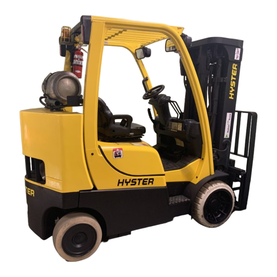
Hyster J004 (S80FT, S80FT-BCS, S100FT, S100FT-BCS,
S120FT, S120FTS, S120FT-PRS) Forklift Service Repair
Manual
Table of
Contents
Previous
Page
Next
Page
1
2
3
4
5
Advertisement
Need help?
Do you have a question about the J004 and is the answer not in the manual?
Ask a question
Questions and answers
Related Manuals for Hyster J004
Forklifts Hyster G024 Service & Repair Manual
(25 pages)
Forklifts Hyster H4.0FT5 Service & Repair Manual
(25 pages)
Forklifts Hyster J006 Service & Repair Manual
(25 pages)
Forklifts Hyster H135FT Service & Repair Manual
(25 pages)
Forklifts Hyster J007 Service & Repair Manual
(25 pages)
Forklifts Hyster J019 Service & Repair Manual
(25 pages)
Forklifts Hyster J35XMT Service & Repair Manual
(21 pages)
Forklifts Hyster J1.60XMT Service & Repair Manual
(20 pages)
Forklifts Hyster J40XM Safety Precautions Maintenance And Repair
Instrument cluster (26 pages)
Forklifts Hyster J2.00-3.20XM Manual
(20 pages)
Forklifts Hyster H/S/1.50-1.75XM Manual
(90 pages)
Forklifts Hyster J90XN Service & Repair Manual
(27 pages)
Forklifts Hyster J100XN Service & Repair Manual
(27 pages)
Forklifts Hyster A276 Troubleshooting Manual
(68 pages)
Forklifts Hyster J160 Manual
(25 pages)
Forklifts Hyster A216 Service & Repair Manual
(21 pages)
This manual is also suitable for:
S80ft
S80ft-bcs
S100ft
S100ft-bcs
S120ft
S120fts
...
Show all
S120ft-prs
Print
Rename the bookmark
Delete bookmark?
Delete from my manuals?
Login
Sign In
OR
Sign in with Facebook
Sign in with Google
Upload manual
Upload from disk
Upload from URL


Need help?
Do you have a question about the J004 and is the answer not in the manual?
Questions and answers