Table of Contents
Advertisement
Quick Links
Advertisement
Table of Contents

Related Manuals for Focusrite ISA 828


Summary of Contents for Focusrite ISA 828
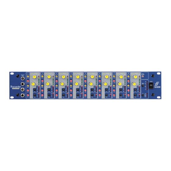
- Page 1 ISA 828 User Guide Mode d’emploi FA0145-04...
- Page 2 WARNINGS & CAUTIONS THE APPARATUS SHALL NOT BE EXPOSED TO DRIPPING OR SPLASHING, AND NO OBJECTS FILLED WITH LIQUIDS, SUCH AS VASES, SHALL BE PLACED ON THE APPARATUS VENTILATION SHALL NOT BE IMPEDED BY COVERING THE VENTILATION OPENINGS WITH ITEMS, SUCH AS NEWSPAPERS, CLOTHS, CURTAINS ETC.
-
Page 3: Table Of Contents
Contents Getting Started and Powering Up ..4 Front Panel ......5 Rear Panel . -
Page 4: Getting Started And Powering Up
A 2-way switch labelled Power supplies power to the unit, providing the supplied IEC mains lead is connected to the input on the rear panel. Make sure that the ISA 828 is turned on before powering up any devices connected to the outputs. -
Page 5: Front Panel
Front Panel Instrument Inputs (Inputs 1-4) Input Stage Activates a gain range of 30-60 across the Gain (stepped) dial (the default is 0-30) Phantom Power switch Eight numbered sections are included on the front panel for setting up each of the eight analogue inputs. Input Pressing Input steps through each of the three inputs, as indicated by the corresponding LEDs. - Page 6 Mode 1 Mic Gain Range 0-30 With the 30-60 switch off, the stepped gain dial operates over a gain range of 0dB to +30dB, the level of gain chosen being indicated on the front panel by the outer arc of yellow numbers around the gain knob. Mode 2 Mic Gain Range 30-60 With the 30-60 switch on (illuminated), the stepped gain dial operates over a gain range of 30dB to 60dB, the level of gain chosen being indicated on the front panel by the outer arc of yellow numbers around the gain knob.
- Page 7 LEDs. By selecting different values for the impedance of the ISA 828 transformer input, the performance of both the ISA 828 pre-amp and the microphone connected can be tailored to set the desired level and frequency response. The impedance values are as follows: Low –...
-
Page 8: Rear Panel
Mode 2. Meters Pre ADC switch engaged This is the mode to use when the analogue input signals are being routed to other hardware devices (such as dynamics processors) using the analogue outputs/ADC Input on the rear panel (acting as sends/returns) before converting to digital. - Page 9 Analogue Inputs On the rear panel, there are 8 XLR inputs for connecting microphones and 8 1/4” TRS inputs for line-level sources. Each one is numbered accordingly and corresponds to the relevant section on the front panel. All 3-pin XLR balanced audio connectors are wired as follows: Pin 1: Screen/Chassis...
-
Page 10: Digital Options
Digital Options The optional ADC can be retrofitted to a standard ISA 828 at any time. No engineering experience is required as the card can be fitted easily by the user. Full fitting instructions for this option are included along with the ADC. - Page 11 AES 1+ 24-bit/192kHz ADAT™ interface operation The card provides digital outputs for all eight ISA 828 channels, which operate over the sample frequency ranges 44.1-192kHz. The card features two ADAT™-type ‘lightpipe’ output connectors. For speeds up to 48kHz, both connectors transmit all 8 channels simultaneously.
-
Page 12: Applications
Pressing EXT allows the ISA 828 to be slaved to an external word clock source, connected to the word clock input on the rear panel. Selecting 256x allows the ISA 828 to be slaved to an external clock running at 256 times faster than the sample frequency and enables connection to systems such as the Digidesign ‘Superclock’... - Page 13 Various microphone/ISA 828 pre-amp impedance combinations can be tried to achieve the desired amount of colouration for the instrument or voice being recorded. To understand how to use the impedance selection creatively, it may be useful to read the following section on how the microphone output impedance and the mic preamp input impedance interact.
-
Page 14: Signal Connections
Impedance Setting Quick Guide In general, the following selections will yield these results: High mic pre-amp impedance settings · Will generate more overall level · Will tend to make the low- and mid-frequency response of the microphone flatter · Will improve the high-frequency response of the microphone. Low pre-amp impedance settings ·... - Page 15 Recording with Inserts Focusrite Compounders (Stereo Compression) x 4 Analogue I/Ps ISA 828 has all eight Insert switches engaged Digital Storage Medium Recording from AES Outputs 1-8 to Pro Tools HD™ at 192kHz AES/EBU 25-pin Inputs (requires 2 cards) Cable pinout according...
-
Page 16: Faqs
Q: Which applications is the ISA 828 suitable for? A: The ISA 828 can be used as a multi-channel high quality front end for Digital Audio Workstations, allowing multi- channel recording to HD. Equally, it can be used simply as the perfect interface or A/D converter for synths/other line- level devices. - Page 17 Q: Is there an optional digital input card? A: No, because the ISA 828 is primarily a ‘front end’ product. In other words, the only devices that are likely to be connected to the 828’s inputs are analogue sound sources such as microphones, guitars etc.
-
Page 18: Specifications
Specifications Mic Input Response • Gain range = 0dB to 60dB in 10dB steps • Input Impedance, variable as follows:- Switched Impedance setting Equivalent Input Impedance at 1kHz ISA 110 1400 Med (Medium) 2400 High 6800 • EIN (equivalent input noise) = -126dB measured at 60dB of gain with 150 Ohm terminating impedance and 22Hz/22kHz bandpass filter •... -
Page 19: Warranty
Warranty All Focusrite products are covered by a warranty against manufacturing defects in material or craftsmanship for a period of one year from the date of purchase. Focusrite in the UK, or its authorised distributors worldwide, will do their best to ensure that any fault is remedied as quickly as possible. - Page 20 828 (default jumper positions shown on Appendix 2) and 2 Digital cards must be fitted in the HD192 interface. A 25-pin to two 25-pin cable must then be used, with the following pinout: Pin No. ISA 828 ADC Connector AES 8+ AES 7-...
- Page 21 Appendix 2 Digital Card Jumper Positions - Disabling AES Outputs 5-8 Four jumpers on the digital card can be made to disable channels 5-8 on the AES Output. This is so that a standard 25-pin to 25-pin Pro Tools™ cable can be used to record channels 1-4 at 192kHz. (Half of the connections on the Digidesign Digital Input are used for receiving and the other half for transmitting.) For more information, consult the relevant section of the Pro Tools™...
Need help?
Do you have a question about the ISA 828 and is the answer not in the manual?
Questions and answers