
Related Manuals for Emerson RXi2-UP


Summary of Contents for Emerson RXi2-UP
- Page 1 Hardware Reference Manual GFK-3047D Oct 2021 RXi2-UP Industrial PC HARDWARE REFERENCE MANUAL...
- Page 2 These instructions do not purport to cover all details or variations in equipment, nor to provide for every possible contingency to be met during installation, operation, and maintenance. The information is supplied for informational purposes only, and Emerson makes no warranty as to the accuracy of the information included herein. Changes, modifications, and/or improvements to equipment and specifications are made periodically and these changes may or may not be reflected herein.
-
Page 3: Table Of Contents
RXi2-UP IPC Hardware Reference Manual Contents GFK-3047D Oct 2021 Contents Section 1: Introduction ............1 Revisions to this Manual ................1 Related Documentation ................1 Features ......................1 Section 2: Capability and Compatibility ......4 Software Requirements ................. 4 Features ......................4 Section 3: Unpacking and Inspection ........ - Page 4 RXi2-UP IPC Hardware Reference Manual Contents GFK-3047D Oct 2021 5.7.3 Setting up Boot Priority ..............29 5.7.4 Restoring UEFI Settings ..............29 5.7.5 UEFI Passwords ................. 29 5.7.6 Secure Boot Configuration ..............29 RTC Battery Replacement ................30 5.8.1 To replace the Real-Time Clock (RTC) battery ........30 Section 6: Hardware Interface ..........
- Page 5 RXi2-UP IPC Hardware Reference Manual Contents GFK-3047D Oct 2021 8.2.4 Altitude .................... 51 8.2.5 Regulations and Certification ............52 8.2.6 Battery ..................... 52 Technical Specifications ................53 Section 9: Troubleshooting ..........54 Movicon.NExT License File Recovery in Windows 10 ........54 Appendix A: Open Source Software (OSS) List (V0.x) ....
-
Page 6: Introduction
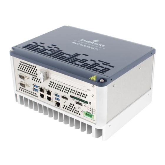
RXi2-UP Industrial PC Datasheet 00813-0100-0120 Features The RXi2-UP IPC industrial computing platform delivers compact, rugged, high- performance computing and high-performance graphics capabilities to run Human- machine Interface (HMI), historian, and analytics applications for real-time control of operations. It offers expansion options of 1, 2, or 4 (mini and low profile) PCI Express (PCIe) slots and CFast storage. - Page 7 SRC SATA riser board for additional 2.5-inch mass storage devices support • Industrial grade enclosure with heat sink for the module and carrier components This chapter describes the features, capabilities, and compatibilities of the RXi2-UP IPC and its components. Figure 1: 0-Slot RXi2-UP IPC...
- Page 8 RXi2-UP IPC Hardware Reference Manual Section 1 GFK-3047D Oct 2021 Figure 3: 2-Slot RAID RXi2-UP IPC Figure 4: 4-Slot RXi2-UP IPC Figure 5: 4-Slot RAID RXi2-UP IPC Introduction...
-
Page 9: Capability And Compatibility
Microsoft® Windows® 10 Professional 64-Bit • Linux® Kernel 4.8 Features RXi2-UP IPC module features are as follows: • 7th Generation Intel Core Processor and Intel Xeon Processor E3-1200 v6 product line i5-7442EQ 25W 4c/4t HD530 2.1GHz (max 2.9) GHz 6MB, 16GB no ECC ▪... - Page 10 • 5x Gig Ethernet ports (1 from module plus 4 Ethernet controller (4x i210IT) with TimeSYNC IEEE1588 and 802.1AS Alternative 1x GigE and 4x SFP (4x i210IS) (contact Emerson for support) • Mini PCIe slot (half and full size) Unified Infrastructure Management (UIM) interface •...
-
Page 11: Unpacking And Inspection
Unpacking and Inspection CAUTION If the RXi2-UP IPC operates in an enhanced ambient temperature up to 65°C (149 ° F), the surface of the enclosure, especially the heat sink, can reach a temperature of 85°C (185 °F) and above. Be careful and do not touch the RXi2-UP IPC with bare fingers. -
Page 12: Esd And Emi
Any operational system with cables for I/O signals, connectivity, or peripheral devices provides an entry point for ESD and EMI. If Emerson does not manufacture the complete system, including enclosure and cables, it is the responsibility of the system integrator and end-user to protect their system against potential problems. -
Page 13: Unpack And Inspect
If evidence of damage or rough handling is found (usually in the form of bent component leads or loose socketed components), notify the shipping service as soon as possible and contact Emerson for additional instructions. Depending on the severity of the damage, it may be necessary to return the product to the factory for repair. -
Page 14: Handling
Handling WARNING If the RXi2-UP IPC operates with an enhanced ambient temperature up to 65°C (149 ° F), the surface of the enclosure, especially the heat sink, can reach a temperature of 85°C (185 °F) and above. Be careful and do not touch the RXi2-UP IPC with bare fingers. -
Page 15: Mounting
RXi2-UP IPC Hardware Reference Manual Section 4 GFK-3047D Oct 2021 Section 4: Mounting RXi2-UP IPC cooling is designed for the wall-mounted orientation of the box. • Flat wall mounting Flat Wall-Mounting There are two types of wall mounting: • Flat wall mounting with mounting plates •... -
Page 16: Flat Wall Mounting With Mounting Plates
RXi2-UP IPC Hardware Reference Manual Section 4 GFK-3047D Oct 2021 4.1.1 Flat Wall Mounting with Mounting Plates The screws selected for use depend on the nature of the wall. The mounting plates have four drills holes with a diameter of 5.3 mm (0.209 in), so the maximum screw diameter cannot be higher than 5.2 mm (0.205 in). -
Page 17: Flat Wall Mounting Through Wall
RXi2-UP IPC Hardware Reference Manual Section 4 GFK-3047D Oct 2021 4.1.2 Flat Wall Mounting Through Wall To mount the IPC with screws from the wall side, place drill holes in the wall. Refer to the following figure for the positions for the holes. The thread in the enclosure is an M6 with a usable thread length of 15 mm (0.60 in). -
Page 18: Installation And Startup
Do not restore power until all components are fitted correctly into the system and all connections have been made properly. Required Materials The following items are required to start the RXi2-UP IPC in a standard configuration: • Power supply •... -
Page 19: Power Supply
Minimum System Requirements The RXi2-UP IPC has been thoroughly tested and is nearly ready for use in the target system. To verify operation for the first time, Emerson recommends that you only configure a minimal system. It is not necessary to have disk drives, a flash disk, or other accessories connected to perform the Power-On Self-Test (POST). -
Page 20: Installation Procedures
Oct 2021 Installation Procedures 5.5.1 PCIe Board Installation Install a PCIe board into the RXi2-UP IPC using the following procedure. To install the PCIe board WARNING Verify that the power supply is turned OFF while installing boards or modules into the RXi2-UP IPC. - Page 21 RXi2-UP IPC Hardware Reference Manual Section 5 GFK-3047D Oct 2021 Remove the PCIe support bracket screws (qty 4) (Tx10). Figure 12: PCIe Support Bracket Screws Remove the PCIe support bracket. Figure 13: Removed PCIe Support Bracket and Screws Installation and Startup...
- Page 22 RXi2-UP IPC Hardware Reference Manual Section 5 GFK-3047D Oct 2021 Remove the PCIe slot bracket. Figure 14: Removed PCIe Slot Bracket Insert the PCIe board bracket into the slot. Figure 15: PCIe Board Bracket Inserted into Slot Installation and Startup...
- Page 23 RXi2-UP IPC Hardware Reference Manual Section 5 GFK-3047D Oct 2021 Insert the PCIe board bracket into the PCIe connector at the riser board. Ensure that the board fits properly into the connector and is well connected. Figure 16: PCIe Board Bracket Inserted into PCIe Connector Reattach the PCIe support bracket.
- Page 24 RXi2-UP IPC Hardware Reference Manual Section 5 GFK-3047D Oct 2021 Reattach the four PCIe support bracket screws (Tx10 [0.6 Nm/5.3 in lb]). Figure 18: Reattached PCIe Bracket Screws Adjust the cardholder. Figure 19: Card Holder Adjustment Installation and Startup...
-
Page 25: Mini Pcie Add-On Board Installation
The information described in this section applies to service technicians only. The Mini PCIe (mPCIe) board is connected to the RXi2-UP IPC by inserting the board into either a full-size slot or a half-size slot, depending on the size of the Mini PCIe board you are inserting. - Page 26 RXi2-UP IPC Hardware Reference Manual Section 5 GFK-3047D Oct 2021 Adjust the slot size to allow for the size of the Mini PCIe board being inserted (Tx8 [0.6 Nm/5.3 in lb]). Figure 21: Short Position for mPCIe Bracket Figure 22: Long Position for mPCIe Bracket Insert the Mini PCIe board into the connector slot.
- Page 27 Mount Mini PCIe board into the connector slot using standard screws (Tx8 [0.6 Nm/5.3 in lb]) screw: ISO14583 M2.5 x 6 or M2.5 x 5. Figure 24: Mini PCIe Board Mounted to RXi2-UP IPC SIM Card Interface Installation Note: Please note that when installing plug-in cards with wireless transmission capabilities, such as a cellular modem or WiFi adapters, the user is responsible for updating CE, FCC and any other required certifications of the final unit.
- Page 28 RXi2-UP IPC Hardware Reference Manual Section 5 GFK-3047D Oct 2021 To Install the SIM card WARNING Verify that the power supply is turned OFF while installing boards or modules into the RXi2-UP IPC. Open SIM card holder by moving the upper part in the OPEN → direction (as shown on the part).
- Page 29 RXi2-UP IPC Hardware Reference Manual Section 5 GFK-3047D Oct 2021 Insert the SIM card. Figure 27: SIM Card Inserted Lock the SIM card into position by moving the upper part in the LOCK ← direction (as shown on the part).
-
Page 30: M.2 A-Key Add-On Board Installation
M.2 A-Key Add-on Board Installation ATTENTION The information described in this section applies to service technicians only. The M.2 board is connected to the RXi2-UP IPC by inserting the board with a form factor of 2230. To Install the M.2 A-Keyboard... - Page 31 GFK-3047D Oct 2021 Mount the M.2 A-Key board into the connector slot using standard screws (Tx8 [0.45 Nm/5 in lb]), screw: ISO14583 M2.5 x 6, or M2.5 x 5. Figure 31: M.2 A-Key Mounted to RXi2-UP IPC Installation and Startup...
-
Page 32: M.2 M-Key Add-On Board Installation
ATTENTION The information described in this section applies to service technicians only. The M.2 board is connected to the RXi2-UP IPC by inserting the board with the form factor of 2242, 2260, 2280, or 22110. To install the M.2 M-key board... - Page 33 Figure 33: M.2 M-Key Insertion into Connector Slot Mount the M.2 M-Key board into the connector slot using standard screws (Tx8 [0.45 Nm/5 in lb]) screw: ISO14583 M2.5 x 6 or M2.5 x 5. Figure 34: M.2 M-Key Mounted to RXi2-UP IPC Installation and Startup...
-
Page 34: Initial Startup
A few seconds after powering up, the RXi2-UP IPC system BIOS banner displays on the screen. If you do not see any error messages up to this point, the RXi2-UP IPC is running properly and ready to be configured for your application. -
Page 35: Rtc Battery Replacement
To replace the Real-Time Clock (RTC) battery Remove power from the RXi2-UP IPC. Loosen the four captive screws on the RXi2-UP IPC’s top cover and remove it. Figure 35: RTC Battery (Removed Top Cover) Remove the RTC battery from the retaining clip. -
Page 36: Hardware Interface
RXi2-UP IPC Hardware Reference Manual Section 6 GFK-3047D Oct 2021 Section 6: Hardware Interface This chapter describes the hardware interface used in the RXi2-UP IPC. The following diagram provides an overview of the way the hardware interface is used. Hardware Interface... - Page 37 RXi2-UP IPC Hardware Reference Manual Section 6 GFK-3047D Oct 2021 Figure 36: RXi2-UP IPC Hardware Interface Overview Hardware Interface...
-
Page 38: Interface
Figure 37: RXi2-UP IPC Hardware Interface Overview (2-slot Option) 6.1.1 Status LEDs The RXi2-UP IPC contains a set of status LEDs to indicate various functions. The CEC09 provides LEDs on the front panel, in a location near the power connector and power button. Table 6-1... -
Page 39: Power Button
Pressing (short push) the power button triggers the operating system to shut down (Power State S5). If the operating system does not immediately shut down, press and hold the Power button for more than 5 seconds to force the RXi2-UP IPC to shut down immediately without support from the operating system. -
Page 40: Ethernet Ports (Eth1, Eth2, Eth3, Eth4, Eth5)
6.1.4 Ethernet Ports (Eth1, Eth2, Eth3, Eth4, Eth5) Five Ethernet interface ports are available on the RXi2-UP IPC. They are located on the front panel. Ethernet interface requires the use of a CAT 5 cable for proper operation with 100/1000BaseT. -
Page 41: Display Port
RXi2-UP IPC Hardware Reference Manual Section 6 GFK-3047D Oct 2021 Table 6-4 ETH5 LEDs LED on RJ–45 Jack LED Status Indication #GBE5_LINK Solid = Any LINK Yellow Blinking = ACTIVITY #GBE5_ACT Orange #GBE5_LINK100 LINK100 Green #GBE5_LINK1000 LINK1000 Figure 6-41 RXi2-UP IPC GBE 6.1.6... -
Page 42: Usb 3.0 Connectors
RXi2-UP IPC Hardware Reference Manual Section 6 GFK-3047D Oct 2021 Table 6-5 Display Port Interface Signals Signal Name TxD0+/- TxD1+/- TxD2+/- TxD3+/- 10/12 AUXSEL CLK/AUX+ DAT/AUX- HTPLG DP_VCC Note: DP_VCC is fused with 2 A fuse, but for normal operation do not exceed 1 A at this pin. -
Page 43: Power Connectors
SSTX+ 6.1.8 Power Connectors The power inlet into the RXi2-UP IPC is a Phoenix contact Base strip - MSTB 2.5/ 3-GF - 1776702 connector. The corresponding plug is a type FKCN 2.5/ 3-STF - 1732975 from Phoenix contact. Figure 6-44... -
Page 44: Internal Sata Connector
6.1.10 CFast Connector Located on the front of the RXi2-UP IPC is a CFast Type 1 flash connector. CFast is a variant of a CompactFlash that supports a higher maximum transfer rate than current Compact Flashcards. Standard CFast cards can be used for the storage of data or the operating system. - Page 45 RXi2-UP IPC Hardware Reference Manual Section 6 GFK-3047D Oct 2021 Figure 46: Serial Ports – 2-Slot Variant Figure 47: Serial Ports – 4-Slot Variant Table 6-9 Serial Ports Signal Name RS–232 Pin RS–422 / RS–485 Pin Hardware Interface...
-
Page 46: Sata 2.5 Inch Drive Tray Replacement
RXi2-UP IPC Hardware Reference Manual Section 6 GFK-3047D Oct 2021 Figure 48: Pin Assignment For RS–422 and RS–485-4 wire modes, connect the corresponding RX+/- with the TX+/- of the counterpart and vice versa. For RS–485-2 wire mode connect RX+ and TX+ with the + line of the cable and the RX- and the TX- together with the –... - Page 47 RXi2-UP IPC Hardware Reference Manual Section 6 GFK-3047D Oct 2021 Figure 49: 2.5 inch SATA Drive Device Tray Location 2. Insert your finger under the handle and carefully remove the storage device tray from the mounted position. Figure 50: Removing Storage Device Tray from Mounted Position...
- Page 48 RXi2-UP IPC Hardware Reference Manual Section 6 GFK-3047D Oct 2021 3. Pull down until the device tray is as fully open as possible. Figure 51: Storage Device Tray Fully Open Position 4. Remove the hard disk tray completely from the unit.
- Page 49 RXi2-UP IPC Hardware Reference Manual Section 6 GFK-3047D Oct 2021 5. Unscrew the four mounting screws and separate the hard drive from the tray. Figure 53: Storage Device Tray Screws 6. Insert the replacement hard drive and screw in the four mounting screws to mount it.
- Page 50 RXi2-UP IPC Hardware Reference Manual Section 6 GFK-3047D Oct 2021 Figure 55: Tray Insertion 1. Insert the tray until it is fully and firmly seated. Figure 56: Inserted Tray Note: You can lock each SSD tray using the provided key.
-
Page 51: Additional Devices
The RXi2-UP IPC offers Non-Volatile Random Access Memory (NVSRAM) as a mPCIe board add-on option that is automatically backed up when the RXi2-UP IPC is switched off or loses power. It is not supplied with battery power but an exhausted Lithium coin battery will not result in a loss of data. -
Page 52: Hardware And Firmware Programmable Devices
RXi2-UP IPC Hardware Reference Manual Section 7 GFK-3047D Oct 2021 Section 7: Hardware and Firmware Programmable Devices This chapter describes the hardware and firmware programmable devices of the CEC09 carrier board and the bCOM6L20 module. SMBUS Devices Table 7-1 SMBus Devices... -
Page 53: Pci Routing
COMe PCIe Ethernet #4 COMe PCIe M.2 A-Key COMe PCIe UART COMe PCIe mPCIe PCI Routing The PCI routings in an RXi2-UP IPC are defined in the following table. Table 7-4 PCI Routing Connected Device (GPU Function Vendor Bus/Dev/Func Dependent) bCOM6L20 —... - Page 54 RXi2-UP IPC Hardware Reference Manual Section 7 GFK-3047D Oct 2021 Connected Device (GPU Function Vendor Bus/Dev/Func Dependent) — Intel PMC 8086 0/1F/2 — Intel HD Audio 8086 0/1F/3 — Intel SMBUS 8086 0/1F/4 — I219-LM — 8086 0/1F/6 CEC09 Riser slot —...
-
Page 55: Specifications
This chapter provides specifications and useful information for the RXi2-UP IPC. Power Consumption The RXi2-UP IPC should be connected to a single main power supply with limited output power (max 250 V A) with a nominal output voltage of 24 V dc (±25%), SELV according to IEC60950-1. -
Page 56: Environmental Specifications
Please contact technical support for further guidance. 8.2.2 Shock and Vibration without 2.5 inch Mass Storage The RXi2-UP IPC without 2.5-inch mass storage options is designed to meet the shock and vibration values listed in the following table. Table 8-4 Shock and Vibration Specifications without Additional 2.5 inch Mass... -
Page 57: Regulations And Certification
The RXi2-UP IPC contains a BR2032 lithium coin battery. The maximum current used by the bCOM6L20 module is 6uA. Depending on the operating hours and temperature, the estimated battery life is 2 to 10 years. Battery current is not used when the RXi2-UP IPC is supplied with 24 V. -
Page 58: Technical Specifications
4x USB 2.0 Standard ports – External USB Interface 2x USB 2.0 Standard ports – Internal RXi2-UP 0/1/2–slot: RS-232 or opto-coupled 422/485 Serial Communications RXi2-UP 4–slot: RS-232 and opto-coupled 422/485 Internal Mini PCIe board slot, half and full length (for WLAN, LTE) Internal M.2 A-Key slot, form factor 2230 (WLAN) -
Page 59: Troubleshooting
You will be shown one or more MAC addresses, please copy the first MAC address in the list and email it along with the Serial Number to Emerson Customer Care. (The serial number can be found on the label located on the left side of the unit, indicated by SN: xxxxxxxx) e. -
Page 60: Appendix A: Open Source Software (Oss) List (V0.X)
(Emerson) provides the following software package installations. This code is provided on an as-is basis, and Emerson makes no representations or warranties for the use of this code independent of any Emerson-provided software or services. Refer to the licenses and copyright notices files for each package for specific license terms that apply to each software bundle associated with this product release. -
Page 61: Appendix B: Acronyms And Abbreviations
RXi2-UP IPC Hardware Reference Manual Appendix B GFK-3047D Oct 2021 Appendix B: Acronyms and Abbreviations ACPI Advanced Configuration and Power Interface Accelerated Processing Unit Advanced Micro Devices BIOS Basic Input Output System Computer-on-module Display Data Control Digital Display Interface Display Port... - Page 62 RXi2-UP IPC Hardware Reference Manual Appendix B GFK-3047D Oct 2021 Time Division Multiplex Thermal Design Power Trusted Platform Module TMDS Transition Minimized Differential Signaling UART Universal Asynchronous Receiver Transmitter UEFI Universal Extensible Firmware Interface Universal Serial Bus Video Graphics Adapter...
-
Page 63: Appendix C: Glossary
An application-specific circuit board that accepts a COM Express module. Conformité Européenne (European conformity) CCTV Closed Circuit Television Text in Courier font indicates a command entry or output from an Emerson Courier Font embedded PC product using the built-in character set CTDP... - Page 64 RXi2-UP IPC Hardware Reference Manual Appendix C GFK-3047D Oct 2021 Word Description Gigabit Ethernet Giga Transfer I/O HDCP High-Bandwidth Digital Content Protection Hexadecimal values Represented as digits followed by ʹhʹ (for example:0Ch) (base 16) Hexadecimal values Represented as digits preceded by ʹHʹ (for example: H0C)
- Page 65 RXi2-UP IPC Hardware Reference Manual Appendix C GFK-3047D Oct 2021 Word Description SATA Serial AT Attachment: serial-interface standard for hard disks. Single Board Computer SB-TSI Side Band Temperature Sensor Interface System Control Interrupt Serial Presence Detect refers to serial EEPROM on DRAMs that has DRAM...
-
Page 66: General Contact Information
Note: If the product is purchased through an Authorized Channel Partner, please contact the seller directly for any support. Emerson reserves the right to modify or improve the designs or specifications of the products mentioned in this manual at any time without notice. Emerson does not assume responsibility for the selection, use, or maintenance of any product.
Need help?
Do you have a question about the RXi2-UP and is the answer not in the manual?
Questions and answers