
Related Manuals for Wilo 490 Series


Summary of Contents for Wilo 490 Series
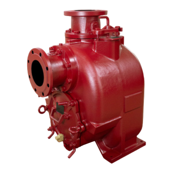
- Page 1 A WILO BRAND 490 Series SXT 3”-10” Self-Priming Pumps Installation and Operating Manual...
-
Page 2: Table Of Contents
TABLE OF CONTENTS INTRODUCTION ............................. - 3 - SAFETY SECTION A ..........................- 4 - INSTALLATION SECTION B ........................ - 5 - Pump Dimensions ..........................- 6 - PREINSTALLATION INSPECTION ......................- 9 - POSITIONING PUMP ..........................- 9 - Lifting .............................. - Page 3 PUMP MAINTENANCE AND REPAIR SECTION E ..............- 24 - PERFORMANCE CURVE ......................... - 24 - ILLUSTRATION............................- 28 - PARTS LIST ..............................- 29 - PUMP AND SEAL DISASSEMBLY AND REASSEMBLY .............. - 29 - Back Cover and Wear Plate Removal ..................- 33 - Rotating Assembly Removal .....................
-
Page 4: Introduction
INTRODUCTION Thank You for purchasing an American-Marsh Pump. Read this manual carefully to learn how to safely install and operate your pump. Failure to do so could result in personal injury or damage to the pump. Because pump installations are seldom identical, this manual cannot possibly provide detailed instructions and precautions for every aspect of each specific application. -
Page 5: Safety Section A
NOTE: Instructions to aid in installation, operation, and maintenance or which clarify a procedure. SAFETY SECTION A This information applies to the 490 Series SXT 3”-10” pumps. AMP has no control over or particular knowledge of the power source which will be used. Refer to the manual accompanying the power source before attempting to begin operation. -
Page 6: Installation Section B
Do not operate the pump against a closed discharge valve for long periods of time. If operated against a closed discharge valve, pump components will deteriorate, and the liquid could come to a boil, build pressure, and cause the pump casing to rupture or explode. -
Page 7: Pump Dimensions
Pump Dimensions See Figures 1 for the approximate physical dimensions of the pump model SXT 3”-10”. OUTLINE DRAWING SXT 3X3 - 6 - IOM 490 SXT 3”-10”_0222... - Page 8 SXT 6X6 - 7 - IOM 490 SXT 3”-10”_0222...
- Page 9 SXT 8X8 SXT 10X10 - 8 - IOM 490 SXT 3”-10”_0222...
-
Page 10: Preinstallation Inspection
PREINSTALLATION INSPECTION The pump assembly was inspected and tested before shipment from the factory. Before installation, inspect the pump for damage which may have occurred during shipment. Check as follows: Inspect the pump for cracks, dents, damaged threads, and other obvious damage. b. -
Page 11: Clearance
Clearance Clearance recommendations for removal and access of interior pump parts. PUMP SIZE MINIMAL CLEARANCE FOR RECOMMENDED CLEARANCE REMOVAL OF FRONT COVER FOR REMOVAL OF COVER AND EASY ACCESS TO THE PUMP INTERIOR 9 inches (229 mm) 18 inches (457 mm) 10 inches (254 mm) 18 inches (457 mm) 11 inches (279,4 mm) -
Page 12: Suction Lines
SUCTION LINES To avoid air pockets, which could affect pump priming, the suction line must be as short and direct as possible. When operation involves a suction lift, the line must always slope upward to the pump from the source of the liquid being pumped; if the line slopes down to the pump at any point along the suction run, air pockets will be created. -
Page 13: Suction Line Positioning
If it is necessary to position inflow close to the suction inlet, install a baffle between the inflow and the suction inlet at a distance 1 1/2 times the diameter of the suction pipe. The baffle will allow entrained air to escape from the liquid before it is drawn into the suction inlet. If two suction lines are installed in a single sump, the flow paths may interact, reducing the efficiency of one or both pumps. -
Page 14: Discharge Lines
DISCHARGE LINES Siphoning Do not terminate the discharge line at a level lower than that of the liquid being pumped unless a siphon breaker is used in the line. Otherwise, a siphoning action causing damage to the pump could result. Valves If a throttling valve is desired in the discharge line, use a valve as large as the largest pipe to minimize friction losses. -
Page 15: Automatic Air Release Valve
If the installation involves a flooded suction such as a below‐ground lift station. A pipe union and manual shut‐off valve may be installed in the bleed line to allow service of the valve without shutting down the station, and to eliminate the possibility of flooding. If a manual shut‐off valve is installed anywhere in the air release piping, it must be a full‐opening ball type valve to prevent plugging by solids. -
Page 16: Alignment
Figure 3. Typical Automatic Air Release Valve Installation Connect the valve outlet to a bleed line which slopes back to the wet well or sump. The bleed line must be the same size as the outlet opening or larger, depending on which Air Release Valve is being used. -
Page 17: Coupled Drives
occur in transit and handling. Pumps must be checked and realigned before operation. Before checking alignment, tighten the foundation bolts. The pump casing feet and/or pedestal feet, and the driver mounting bolts should also be tightly secured. When checking alignment, disconnect the power source to ensure that the pump will remain inoperative. -
Page 18: Drive Belts
Check parallel adjustment by laying a straightedge across both coupling rims at the top, bottom, and side. When the straightedge rests evenly on both halves of the coupling, the coupling is in horizontal parallel alignment. If the coupling is misaligned, use a feeler gauge between the coupling and the straightedge to measure the amount of misalignment. -
Page 19: Operation Section C
OPERATION SECTION C Review all SAFETY information in Section A. Follow the instructions on all tags, labels and decals attached to the pump. This pump is designed to handle liquids containing large, entrained solids and slurries. Do not attempt to pump volatile, corrosive, or flammable liquids which may damage the pump or endanger personnel as a result of pump failure. -
Page 20: Operation
is not within the specified limits (see the curve on page SECTION E), check the direction of power source rotation before further troubleshooting. If an electric motor is used to drive the pump, remove V‐belts, couplings, or otherwise disconnect the pump from the motor before checking motor rotation. Operate the motor independently while observing the direction of the motor shaft, or cooling fan. -
Page 21: Strainer Check
Allow an over‐heated pump to completely cool before servicing. Do not remove plates, covers, gauges, or fittings from an over‐heated pump. Liquid within the pump can reach boiling temperatures, and vapor pressure within the pump can cause parts being disengaged to be ejected with great force. After the pump completely cools, drain the liquid from the pump by removing the casing drain plug. -
Page 22: Cold Weather Preservation
Do not operate the pump against a closed discharge throttling valve for long periods of time. If operated against a closed discharge throttling valve, pump components will deteriorate, and the liquid could come to a boil, build pressure, and cause the pump casing to rupture or explode. -
Page 23: Troubleshooting Section D
TROUBLESHOOTING SECTION D TROUBLE POSSIBLE CAUSE PROBABLE REMEDY PUMP FAILS TO PRIME Not enough liquid in casing. Add liquid to casing. See PRIMING. Suction check valve Clean or replace check valve. contaminated or damaged. Air leak in suction line. Correct leak. Lining of suction hose Replace suction hose. -
Page 24: Preventive Maintenance
Review all SAFETY information in Section A. Before attempting to open or service the pump: 1. Familiarize yourself with this manual. 2. Follow approved local Lock-Out/Tag-Out procedures to ensure that the pump will remain inoperative. 3. Allow the pump to completely cool if overheated. 4. -
Page 25: Pump Maintenance And Repair Section E
Preventive Maintenance Schedule Service Interval* Item Daily Wkly Mthly General Condition (Temperature, Unusual Noises or Vibrations, Cracks, Leaks, Loose Hardware, Etc.) Pump Performance (Gauges, Speed, Flow) Bearing Lubrication Seal Lubrication (And Packing Adjustment, If So Equipped) V‐Belts (If So Equipped) Air Release Valve Plunger Rod (If So Equipped) Front Impeller Clearance (Wear Plate) Rear Impeller Clearance (Seal Plate) -
Page 26: Performance Curve
PERFORMANCE CURVES MODEL SXT 3”-10” - 25 - IOM 490 SXT 3”-10”_0222... - Page 27 - 26 - IOM 490 SXT 3”-10”_0222...
- Page 28 * STANDARD PERFORMANCE FOR PUMP MODEL SXT 3”-10” Based on 70°F (21° C) clear water at sea level with minimum suction lift. Since pump installations are seldom identical, your performance may be different due to such factors as viscosity, specific gravity, elevation, temperature, and impeller trim.
-
Page 29: Illustration
ILLUSTRATION Illustration is general for model SXT sizes 3”-8” Figure 1. Pump Model SXT 3”-8” - 28 - IOM 490 SXT 3”-10”_0222... -
Page 30: Parts List
PARTS LIST Pump Model SXT 3”-8” Contact AMP to verify part numbers. Figure 1. Pump Model SXT 3”-8” PART NAME PART NAME PART NAME Capscrew Pipe Plug O-Ring Spring Washer Lifting Bolt / Eye Bolt Seal Plate Pipe Plug Pump Casing Seal Plate Gasket Suction Flange Capscrew... - Page 31 Figure 1. Pump Model SXT 10” - 30 - IOM 490 SXT 3”-10”_0222...
- Page 32 PARTS LIST Pump Model SXT 10” Contact AMP to verify part numbers. Part Name Part Name Part Name Pipe Plug Press Relief Valve Seal Plate Gasket Suction Flange Capscrew Pipe Plug Check Valve Lock Washer Spring Washer Pivot Cap O-Ring Capscrew Lock Washer Wear Plate Assy...
- Page 33 Follow the instructions on all tags, label and decals attached to the pump. This pump requires little service due to its rugged, minimum‐maintenance design. However, if it becomes necessary to inspect or replace the wearing parts, follow these instructions which are keyed to the illustration (see Figure 1) and the accompanying parts lists.
-
Page 34: Back Cover And Wear Plate Removal
Back Cover and Wear Plate Removal (Figure 1) The wear plate (42) is easily accessible and may be serviced by removing the back cover (36). Before attempting to service the pump, remove the pump casing drain plug (43) and drain the pump. Clean and reinstall the drain plug. Remove the hand nuts (34) and studs (35) and pry the back cover and assembled wear plate from the pump casing (28). - Page 35 Install the shaft key (69). Install a lathe dog on the drive end of the shaft (68) with the “V” notch positioned over the shaft key. With the impeller rotation still blocked, see Figure 2 and use a long piece of heavy bar stock to pry against the arm of the lathe dog in a counterclockwise direction (when facing the drive end of the shaft).
-
Page 36: Impeller Removal
(Figure 1) Remove the hardware (63 and 64) securing the rotating assembly to the pump casing. Separate the rotating assembly by pulling straight away from the pump casing. Tie and tag the rotating assembly adjusting flat washers (60) for ease of reassembly. NOTE ‐... -
Page 37: Shaft And Bearing Reassembly And Installation
(Figure 1) When the pump is properly operated and maintained, the bearing housing should not require disassembly. Disassemble the shaft and bearings only when there is evidence of wear or damage. Shaft and bearing disassembly in the field is not recommended. These operations should be performed only in a properly equipped shop by qualified personnel. - Page 38 (Figure 1) Clean the bearing housing, shaft, and all component parts (except the bearings) with a soft cloth soaked in cleaning solvent. Inspect the parts for wear or damage as necessary. Most cleaning solvents are toxic and flammable. Use them only in a well- ventilated area free from excessive heat, sparks, and flame.
-
Page 39: Seal Installation
If heating the bearings is not practical, use a suitably sized sleeve and an arbor (or hydraulic) press to install the bearings on the shaft. When installing the bearings onto the shaft, never press or hit against the outer race, balls, or ball cage. Press only on the inner race. Secure the outboard bearing on the shaft with the bearing snap ring (71). - Page 40 Figure 4. Cartridge Seal Assembly This seal is not designed for operation at temperatures above 160°F (71°C). Do not use at higher operating temperatures If the seal plate (52) was removed, install the seal plate gasket (53). Position the seal plate over the shaft and secure it to the bearing housing with the hardware (57 and 58).
- Page 41 Install the full set of impeller shims (50) provided with the seal and screw the impeller onto the shaft until it is seated against the seal (see Figure 5). Figure 5. Seal Partially Installed Figure 6. Seal Fully Installed Continue to screw the impeller onto the shaft. This will press the stationary seat into the seal plate bore.
-
Page 42: Impeller Installation And Adjustment
Measure the impeller‐to‐seal plate clearance and remove impeller adjusting shims to obtain the proper clearance as described in Impeller Installation and Adjustment. If necessary to reuse an old seal in an emergency, carefully separate the rotating and stationary seal faces from the bellows retainer and stationary seat. A new seal assembly should be installed any time the old seal is removed from the pump. -
Page 43: Rotating Assembly Installation
`Never‐Seez' grease or equivalent to the shaft threads and screw the impeller onto the shaft until tight. Be sure the seal spring seats squarely over the shoulder on the back side of the impeller. NOTE At the slightest sign of binding, immediately back the impeller off, and check the threads for dirt. -
Page 44: Back Cover And Wear Plate Installation And Adjustment
not sold separately. Reach through the back cover opening with the check valve and position the check valve adaptor in the mounting slot in the suction flange (4). Align the adaptor with the flange hole and secure the assembly with the check valve pin (5). NOTE If the suction or discharge flanges were removed, replace the respective gaskets, and secure them to the pump casing with the attaching hardware. - Page 45 Figure 7. Installing and Adjusting Back Cover Screw the four adjusting studs (35) into the tapped holes in the back cover plate until they are just flush with the machined surface on the back side of the cover plate. Align the back cover plate over the two eye bolts (32) and slide it into the pump casing.
-
Page 46: Pressure Relief Valve Maintenance
normal wear between the impeller and wear plate. When all of the adjustment has been used on the back cover side of the pump, an additional 0.125 inch (3,2 mm) of adjustment may be obtained by removing the rotating assembly adjusting flat washers (60). -
Page 47: Lubrication
Reinstall the fill cover and tighten it. Refer to OPERATION, Section C, before putting the pump back into service. LUBRICATION Seal Assembly (Figure 1) Before starting the pump, remove the vented plug (44) and fill the seal cavity with approximately 64 ounces (1.9 liters) of SAE No. 30 non‐detergent oil to the middle of the sight gauge (65, the upper one) and maintain it at the middle of the gauge. -
Page 48: Warranty
Consult the literature supplied with the power source or contact your local power source representative. WARRANTY American-Marsh Pumps guarantees that only high-quality materials are used in the construction of our pumps and that machining and assembly are carried out to high standards. The pumps are guaranteed against defective materials and/or faulty craftsmanship for a period of one (1) year from the date of shipment unless specifically stated otherwise. - Page 49 WILO USA LLC American-Marsh Pumps T +1 262 204 6600 www.wilo-usa.com T +1 901 860 2300 www.american-marsh.com info.us@wilo.com F +1 901 860 2323 amp.cs@wilo.com A WILO BRAND...
Need help?
Do you have a question about the 490 Series and is the answer not in the manual?
Questions and answers