ShopBot PRSalpha Assembly Manual
Hide thumbs
Also See for PRSalpha:
- Assembly manual (100 pages) ,
- Quick start manual (26 pages) ,
- Assembly manual (93 pages)

Related Manuals for ShopBot PRSalpha


Summary of Contents for ShopBot PRSalpha
- Page 1 888-680-4466 • ShopBotTools.com Assembly Guide For PRSalpha and PRSstandard Tools For all PRS tools shipped after 6/15/2017 © Copyright 2017 ShopBot Tools, Inc. page 1...
- Page 2 Assembly Guide for PRS Alpha and Standard Tools • October 5, 2017 © Copyright 2017 ShopBot Tools, Inc. page 2...
-
Page 3: Table Of Contents
Assembly Guide for PRS Alpha and Standard Tools • October 5, 2017 Table of Contents General Safety and Precautions ......................7 PRS Quick-Start Process Flow .......................8 Main Parts of PRSalpha ..........................9 Section 1. Setup and Assembly Overview ..................1-1 Electrical Precautions ......................... 1-1 Other Electrical Precautions ....................... 1-1 Safety............................ - Page 4 Spindle Power Cable ......................8-1 Motors and Signal Cables ....................8-1 Spindle Fan Cable Installation ....................8-2 Proximity Switch Installation ...................... 8-2 X Proximity Switch ........................8-2 Route Wiring ..........................8-3 Pneumatic Air Hoses ........................8-4 © Copyright 2017 ShopBot Tools, Inc. page 4...
-
Page 5: General Safety And Precautions
Never place your hands on the rails of the ShopBot. Be aware that the machine may move unexpectedly in any direction, which can cause serious injury if your hands are in the path of movement. - Page 6 Assembly Guide for PRS Alpha and Standard Tools • October 5, 2017 PRS Tool Assembly Process Flow © Copyright 2017 ShopBot Tools, Inc. page 6...
-
Page 7: Main Parts Of Prsalpha
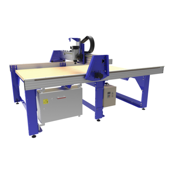
Assembly Guide for PRS Alpha and Standard Tools • October 5, 2017 Main Parts of PRSalpha YZ Car E-chain Spindle Gantry Spoil Board Table Side (Rail) Frame Control Box © Copyright 2017 ShopBot Tools, Inc. page 7... - Page 8 PRS Tool Assembly Process Flow © Copyright 2017 ShopBot Tools, Inc. page 8...
- Page 9 Main Parts of PRSalpha YZ Car E-chain Spindle Gantry Spoil Board Table Side (Rail) Frame Control Box © Copyright 2017 ShopBot Tools, Inc. page 9...
-
Page 10: Section 1. Setup And Assembly Overview
A licensed electrician is required to complete the ShopBot setup. Connecting power to the control box is easiest when the tool is set up and in its final position. If the tool includes a high frequency spindle and/or a vacuum blower, these will also need to be connected by an electrician. -
Page 11: Unpacking The Crate
Section 1: Setup and Assembly Overview • October 5, 2017 Unpacking the Crate ShopBot components arrive in two packages: a large wooden crate, and a long box. Contact the ship- ping company if either piece is missing, or if they do not arrive together. -
Page 12: Major Components
The blue plates on either side of the gantry are referred to as end plates. The YZ car moves across the gantry, and controls the height of the cutter head (either a router or high-speed spindle, depending on the tool). © Copyright 2017 ShopBot Tools, Inc. page 1-3... - Page 13 RPM controller unit, which connects to the PC through a separate USB cable. In most cases, the X-, Y-, and Z-axes will be referred to in respect to the machine. The XY Home Position is also indicated here. © Copyright 2017 ShopBot Tools, Inc. page 1-4...
-
Page 14: Section 2. Table Assembly
The diagrams in this manual depict a 96” x 48” table, the most common ShopBot table size. The table layout may look a little different (fewer or more legs, tool changer bar, etc.) depending on the size and shape of your tool (as well as any accessories included), but the same basic steps will be followed. - Page 15 Legs, cross supports, rails 5/16-18x3/4 Button Head Varies 002033 Used for rails Cap Screw 5/8-11 Hex Nut Varies 000160 1 per table leg 5/8-Table Leveler w/Nut Varies 002926/000862 1 per table leg © Copyright 2017 ShopBot Tools, Inc. page 2-2...
-
Page 16: Tools Required
Remove table sides from packaging and lay them on the floor side-by-side. Locate where the Home Position (X = 0) will be. Note for International Customers: The location of the table legs and cross supports along the X-rails can be adjusted slightly to reflect metric units. © Copyright 2017 ShopBot Tools, Inc. page 2-3... -
Page 17: Mount Table Levelers To Legs
Insert eight T-nuts per table leg into the T-slots in the pattern shown, with the rough side down. Note the line marked earlier for alignment. Ensure to insert the T-nuts for the middle table legs in the T-slots prior to assembling the end table legs. © Copyright 2017 ShopBot Tools, Inc. page 2-4... - Page 18 90 angle. Hand-tighten the top and bottom bolts when the leg is square. Do not tighten other bolts at this time. Repeat this process until all remaining legs are installed. © Copyright 2017 ShopBot Tools, Inc. page 2-5...
-
Page 19: Stabilize With Lower Table Supports
Note: If a leveler foot pops off while lifting the sides in place, simply place the foot under the ball of the hardware and press down on the table side to reseat it. © Copyright 2017 ShopBot Tools, Inc. page 2-6... -
Page 20: Connect Side Assemblies
Snug the bolts enough to preload the lock washers. If the middle table levelers are touching the floor, raise them until they no longer make contact. © Copyright 2017 ShopBot Tools, Inc. page 2-7... -
Page 21: Insert T-Nuts In Bottom Slot
Note: This image shows the approximate T-nut locations for the upper table supports and cross supports for the PRSalpha 96-48 table setup. A table configuration with more table legs or cross supports will require additional T-nuts as indicated on table drawing in the back of this guide. Two T-nuts are needed for every component. - Page 22 Do not snug bolts at this time. Note: The front table support has a ShopBot decal. The middle legs will have upper table supports on both sides of the leg, but only one side uses gussets.
-
Page 23: Secure Table Supports And Cross Supports To Table Sides
Install Cross Supports Use an assistant, clamp(s), or sling(s) to hold the cross supports against bottom of table side for installation. Use a zip tie to line up T-nuts with mounting holes. © Copyright 2017 ShopBot Tools, Inc. page 2-10... -
Page 24: Square The Table Sides
1/16”. If measurements are different, adjust the rear table side. Ensure the bolts holding the cross supports onto the rear table side are loose enough to slide within the grooves. © Copyright 2017 ShopBot Tools, Inc. page 2-11... - Page 25 Once strings are touching, the table should be level. Double check that tool is still square and adjust as necessary. © Copyright 2017 ShopBot Tools, Inc. page 2-12...
-
Page 26: Install Rails
Do not tighten the rear rail at this time. © Copyright 2017 ShopBot Tools, Inc. page 2-13... -
Page 27: Section 3. Gantry Installation
Section 3: Gantry Installation • October 5, 2017 Section 3. Gantry Installation Introduction The gantry will come mostly assembled in the crate. Assistance will be required to safely lift the main assembly and place it on the table assembly. © Copyright 2017 ShopBot Tools, Inc. page 3-1... -
Page 28: Install Gantry
Then, lift it into position over table end, as shown. The gantry wheels should ride on each rail as shown in the image to the right. © Copyright 2017 ShopBot Tools, Inc. page 3-2... -
Page 29: Adjust The Rails
They must hit on both sides of the gantry at the same time. Orient the bolts vertically in the top two slots on the side rail. The stop block should just clear the geared track below the rails. © Copyright 2017 ShopBot Tools, Inc. page 3-3... - Page 30 (opposite from the control box side). The targets will be centered under the proximity switch when the pinion is butted against the stop block. 6 ” 4 ” 8 ” 5 ” © Copyright 2017 ShopBot Tools, Inc. page 3-4...
-
Page 31: Section 4. Cable Carrier Installation
YZ car that will be pre-installed. X-axis cable carriers are included with PRSalpha and PRSstandard machines 96” and above. 48” or 72” X-axis machines use the included “cable carrier kit” to keep the cables organized along the X-axis. Instructions for these should be included in the shipment as a separate document. -
Page 32: Hardware
1/4" Nylock nut 000454 Alternate parts: 12” E-chain trough bracket 003293 5/16-18 T-nuts 002498 X upper E-chain bracket 002156 Parts for X-Axis carrier 6” Z Parts for X-Axis carrier 12” or 24” Z © Copyright 2017 ShopBot Tools, Inc. page 4-2... -
Page 33: X-Axis Cable Carrier
Section 4: Cable Carrier Installation • October 5, 2017 X-Axis Cable Carrier X-axis cable carriers are included with PRSalpha and PRSstandard tools with table sides 96” and up. Table configurations with 48” and 60” are not shipped with X-axis cable carrier kits. -
Page 34: Install The X-Axis Trough: 6" Z-Axis
Attach the trough to the brackets in the same manner as for the tools with the 6” Z. © Copyright 2017 ShopBot Tools, Inc. page 4-4... -
Page 35: Cable Carrier To Upper X Bracket
Section 4: Cable Carrier Installation • October 5, 2017 Cable Carrier to Upper X Bracket The ShopBot PRSalpha and PRSstandard tools come with an X cable bracket pre-installed. Attach one end of the cable carrier to the tab that extends from the X upper cable carrier bracket. -
Page 36: X-Axis Cable Carrier Configurations
Section 4: Cable Carrier Installation • October 5, 2017 X-Axis Cable Carrier Configurations © Copyright 2017 ShopBot Tools, Inc. page 4-6... - Page 37 Section 4: Cable Carrier Installation • October 5, 2017 © Copyright 2017 ShopBot Tools, Inc. page 4-7...
-
Page 38: Section 5. Control Box Installation
Refer to the last page of this section for the alternate orientation. Control box mounting for 18” Z-axis tables is identical to the 6” table. © Copyright 2017 ShopBot Tools, Inc. page 5-1... -
Page 39: Hardware
T-nut standard 5/16-18 ball and 000728 spring pivot insert Nylock Hex Nut 5/16-18 002264 Nut 1/2-13 Z 000440 Flat Washer 1/2" SAE Z 000029 Lock Washer 1/2" Z 000588 Hex Cap Screw 1/2-13x1 1/2" Z5 001956 © Copyright 2017 ShopBot Tools, Inc. page 5-2... - Page 40 Notice that the control box flanges are in front of brackets at both the top and bottom. If the place- ment of the flanges against the brackets is not consistent, the control box will sit at an angle, and not open or close easily. © Copyright 2017 ShopBot Tools, Inc. page 5-3...
-
Page 41: Installation
Lift the control box into place and mount with a button head screw, flat washer, control box flange, through the bracket, flat washer, and a nylock nut for each bracket. © Copyright 2017 ShopBot Tools, Inc. page 5-4... -
Page 42: Alternate Mounting For 12" And 24" Z-Axis Models
The second side rail requires a different lower mounting bracket. This bracket will be installed over the lower cross support with the control box mounting tab pointing down. © Copyright 2017 ShopBot Tools, Inc. page 5-5... -
Page 43: Section 6. Vfd Installation And Spindle
ATCCombinedManual.pdf VFD Installation ShopBot Tools with spindles use a VFD to regulate input power and control rotation speed. There are two major body sizes, 10” and 16”, which are used depending on specific voltage and phases requirements. The supplied bracket will work for either size. -
Page 44: Hardware
An example model number is shown below. The model number is CIMR–VU2A0040GAA. The first bold and underlined number in the written example is the voltage. 2 = 200-240 Vac, 3-phase 4 = 380-480 Vac, 3-phase © Copyright 2017 ShopBot Tools, Inc. page 6-2... -
Page 45: Mounting The 10" Vfd
Section 6: Spindle and VFD Installation • October 5, 2017 Mounting the VFD The 10” VFD mounts to the top and middle set of holes in the middle leg of the ShopBot gantry tools with the VFD 1000 mounting kit. -
Page 46: Spindle Installation
NOTE: Misalignment of the spindle can result in poor cut quality, inaccurate dimensions, and reduced bit life. Squaring the spindle will occur after spoil board installation. © Copyright 2017 ShopBot Tools, Inc. page 6-4... -
Page 47: Section 7. Mounting X-Axis Motors
In this section, the motors to power the X-axis will be installed. The Y and Z-axis motors come preinstalled on the YZ car and will only need minor adjustment. © Copyright 2017 ShopBot Tools, Inc. page 7-1... -
Page 48: Hardware
Inspect the motor cables to make sure they are in good condition and free of cuts or kinks. Remove the plastic sleeve from the motor shaft. © Copyright 2017 ShopBot Tools, Inc. page 7-2... -
Page 49: Identify Motors
Replace motors and confirm pinion/rack alignment. Ensure that the pinion gear set screws are really tight against the shaft Apply a small amount of Lithium grease to each pinion. This will ensure smooth movement and prevent corrosion. © Copyright 2017 ShopBot Tools, Inc. page 7-3... -
Page 50: Mounting Locations
Place each motor in proper location and loosely secure the motor with the mounting hardware and a 5mm hex key. Keep mounting bolts loose so motor plate can slide up and down. © Copyright 2017 ShopBot Tools, Inc. page 7-4... - Page 51 Maintain firm upward pressure (15-20 lbs) with one hand while tightening mounting bolts. If necessary, a second person or quick clamp can hold the motor in position. Once pinion is secure on rack, snug all hardware. © Copyright 2017 ShopBot Tools, Inc. page 7-5...
-
Page 52: Section 8. Wire And Cable Routing
Loosely secure wire bundle to strain relief at bottom of cable carrier on same side as top. Run wire bundle under table and feed through cable entry in right side of control box. © Copyright 2017 ShopBot Tools, Inc. page 8-1... -
Page 53: Spindle Power Cable
Manually move tool along each axis looking for even movement and binding. If binding, resistance, or height tensions occurs, relieve tension and re-secure cables as needed. Clip off all zip tie ends using wire snips. © Copyright 2017 ShopBot Tools, Inc. page 8-2... -
Page 54: Spindle Fan Cable Installation
Thread the proximity switch into the hole until it rests on the target. Back it out 1 to 2 turns so there is a 1/32” – 1/16” (1-2mm) gap between them. Loosely thread the 1/2” nuts onto the proximity switch so that the end plate is “sandwiched” between the two nuts. © Copyright 2017 ShopBot Tools, Inc. page 8-3... -
Page 55: Pneumatic Air Hoses
Certain applications, such as the automatic tool changer (ATC), pneumatic assist, and air drill have one or more air hoses that will route through the cable carrier. To install an air drill, refer to the PRSalpha Air Drill manual located at “http://www.shopbottools.com/ ShopBotDocs/files/PRSalphaAirDrillDV.pdf”... - Page 56 This prevents erroneous signals to the control software. The Z zero clip can be placed on the Wago connector or other convenient location until needed. Secure Cables Tie cables underneath and along crossmember with zip ties. © Copyright 2017 ShopBot Tools, Inc. page 8-5...
- Page 57 Section 9. Control Box Wiring Introduction The wiring instructions for your specific tool should follow this page. ShopBot highly recommends that a licensed electrician hook up the source power according to local code and the wiring and power diagrams included with the tool.
- Page 58 Section 10. Software Installation Introduction ShopBot tools are shipped with three software programs that can program, edit, and run part files. This section covers the installation of all software and provides a basic overview of the ShopBot control software. Additional information and training can be found in the control software “Help” menu as well as ShopBottools.com and Vectric.com.
- Page 59 Refer to “Installing ShopBot Applications” section in “Uninstalling and Reinstalling ShopBot and VCarve Software” document found at http://www.shopbottools.com/ShopBotDocs/files/SBG%20 00441%20Uninstalling%20and%20Reinstalling%20ShopBot%20and%20VCarve%20Software.pdf. Software Overview All programs included with the ShopBot are now installed. The icons below represent how they will appear on the computer desktop. © Copyright 2017 ShopBot Tools, Inc. page 10-2...
- Page 60 The first time the software is connected to a tool, you’ll be prompted to set the default .INI settings file. Locate the ShopBot 3 icon on the desktop or Windows Start menu. Double click on the icon to launch the control software.
- Page 61 Install Control Box Firmware The ShopBot control box is programmed with firmware needed to communicate with the ShopBot 3 control software. This is programmed at the factory for the software version shipped with the tool. If for some reason a different software version is loaded on the control computer, the firmware will need to be updated using this procedure.
- Page 62 If progress bar does not appear, conduct the firmware downloader operation again. ShopBot Control Software Familiarization Easy and Full Modes ShopBot 3 software has two user interface formats; “Easy” and “Full” modes. Easy mode is the © Copyright 2017 ShopBot Tools, Inc. page 10-5...
- Page 63 (right side) is how the machine provides feedback in terms of its coordinates, switch positions, and alarms. ShopBot Command Format Note: This information is provided as a very brief overview to help keep up with the rest of the © Copyright 2017 ShopBot Tools, Inc. page 10-6...
- Page 64 Detailed information and a full list of available commands are available in the ShopBot User Guide. In the ShopBot control software, commands are used to give specific directions to the machine. Any command that directs the machine to move must be followed by parameters. For example, an MX,20 command will “Move”...
- Page 65 Section 11: Secure Table and Spoil Board • October 5, 2017 Section 11. Secure Table and Spoil Board Introduction These instructions are based on a ShopBot PRSalpha 96-48. Larger or smaller table sizes will require additional baseboards and/or cutting material to fit. Hardware...
- Page 66 Have someone help set the MDF sheet(s) onto the base. Place the spoil board on top of baseboard with 1/4” of overlap on all sides. Place clamps and heavy objects onto spoilboard to help glue cure. © Copyright 2017 ShopBot Tools, Inc. page 11-2...
- Page 67 Input 1 – The Z zero plate and the fixed Z zero are connected on this input. When either of these plates are connected to a ground, the circuit is closed and input “1” on the ShopBot position screen will light up. The ShopBot ATC requires that the grounding clip be used during any zeroing of Z-axis.
- Page 68 Tools can also be equipped with a rotational indexer. This allows the tool to be used as a CNC lathe or perform machining operations on more than one side of a part. The B-axis is assigned to the rotational axis and is measured in degrees. © Copyright 2017 ShopBot Tools, Inc. page 12-2...
- Page 69 Important: The Spindle Control window must remain open during operation for the software to com- municate with the VFD and change RPM. Connect the RPM controller to the computer. Do not plug it into the hub alongside the main Shopbot USB; it should go straight into an empty port on your computer.
- Page 70 Move the X-axis off the proximity target using the right arrow key. Note: If the axis is not moved off the proximity target, the other proximity switches will be disabled and the next step will not perform properly. © Copyright 2017 ShopBot Tools, Inc. page 12-4...
- Page 71 1/4” (5mm) before the movement axis reaches its hard stop. When the software receives this input it will stop the tool so that position is not lost. © Copyright 2017 ShopBot Tools, Inc. page 12-5...
- Page 72 Move the corner of the plywood base board at this point and then square it with the table sides. This is the proper position for the spoil board and will allow maximum tool coverage. © Copyright 2017 ShopBot Tools, Inc. page 12-6...
- Page 73 Move machine to 0,0 location. Verify jog by typing JX, 24 or JY, 24. Again, the tool should move 24 inches (or 1000 mm) along the particular axis. If it doesn’t, go back to software setup and chose the correct default setting. © Copyright 2017 ShopBot Tools, Inc. page 12-7...
- Page 74 Pop end caps into place at ends of side rails. The Gantry Tool Assembly is complete. For usage information, see the ShopBot Quick Start Guide, which was provided with tool delivery, and can be found at http://www.shopbottools.com/ShopBotDocs/gantry.htm ShopBot Quick Start Guide For maintenance and troubleshooting information, refer to http://www.shopbottools.com/...
Need help?
Do you have a question about the PRSalpha and is the answer not in the manual?
Questions and answers