
Related Manuals for ARC MCMR-3000


Summary of Contents for ARC MCMR-3000
-
Page 1: Table Of Contents
Issue Date: 21/11/2019 WIRELESS 2 CHANNELS / 2 WAY MODULE RECEIVER MCMR-3000 CONTENTS 1. Overview and features Page 2. 2. Diagrams Page 3. 3. Installation-Wiring Page 4. 4. Pairing / Un-pairing device Page 8. 5. Operation Page 10. 6. Specifications... -
Page 2: Overview And Features
• 2 channels, 1500W each channel resistive load control. • Adaptive mains zero crossing switching. • Total 32 memories,16 memories per channel, first in first out storage maintain. • Scene status memory, create your desired atmosphere. Not compatible to: ARC Code switch system product range OVERVIEW AND FEATURES... -
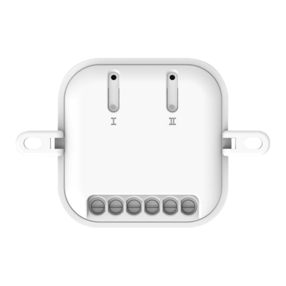
Page 3: Diagrams
Issue Date: 21/11/2019 2. Diagrams Notes for the diagrams: ⚫ Strip wires at least 7mm then connect the wires as per diagrams below, ensure terminals are properly tightened and no bare wire is visible. ⚫ Suitable wire size for terminal is 1.6mm to 2mm DIAGRAMS... -
Page 4: Installation-Wiring
Issue Date: 21/11/2019 3. Installation – Wiring To install module into wall box, break off the mounting tabs. Cut off main power before installing and wiring. 2 Switch – 1 Way Operation INSTALLATION - WIRING... - Page 5 Issue Date: 21/11/2019 1. Remove current Live-in AC 230V wire & Neutral-in AC 230V wires from the existing wall switch. 2. Connect Live-in AC 230V wire & Neutral-in AC 230V wires into module terminal ‘L & N’. 3. Connect wire from module terminal ‘S1’ into mechanical switch 1 ‘L2’ terminal.
- Page 6 Issue Date: 21/11/2019 2 Switch – 2 Way Operation Note, current machnical switch must be compatible for 2 way operations. 1. Remove current Live-in AC 230V wire & Neutral-in AC 230V wires from the existing wall 2. Mechanical Switch 1A / 1B and 2A / 2B must already be connected into ‘L1 & L2’...
- Page 7 Issue Date: 21/11/2019 9. Tighten terminal screw, tidy wires then install module into wall box making sure no bare wires are in front of the module. 10. Before installing the mechanical switch back onto the wall, please proceed to “Pairing Section” below to set up wireless function with a remote control or wall switch.
-
Page 8: Pairing / Un-Pairing Device
Issue Date: 21/11/2019 4. Pairing / Un-pairing Device AIRING Each channel can pair up to 16 memories, first in first out storage maintain. Pairing using LEARNING MODE: 1. Press ‘Learn’ button once (LED on module will flash), this will enter learning mode. - Page 9 Issue Date: 21/11/2019 AIRING Removing single Device: 1. Press ‘Learn’ once (LED on module will flash), this will enter learning mode. 2. With a remote control press the ‘OFF’ button intended to be un-paired; LED on module will flash to confirm that the remote control is un-paired. LEARING EMORY Removing all memory stored in the module.
-
Page 10: Operation
Issue Date: 21/11/2019 5. Operation Operation via remote control. ON/OFF Function: Press the ‘ON’ button on remote control, the load(s) will illuminate. LED on module will light ON for 1 second to indicate a signal is received from a remote-control transmitter. Press the ‘OFF’... -
Page 11: Specifications
Issue Date: 21/11/2019 6. Specifications Input Rating: 230V~50Hz Output Rating: Total 3000W Max. Resistive Load 1500W Max. 6.522A per channel Radio Frequency: 433.92MHz 1W Power consumption: ºC Environment Temperature: 0-40 Range: up to 50 m indoors (Depends on building materials) In accordance with: Low Voltage Directive 2014/35/EU RED Directive 2014/53/EU...
Need help?
Do you have a question about the MCMR-3000 and is the answer not in the manual?
Questions and answers