Advertisement
Quick Links
INSTALLATION INSTRUCTIONS
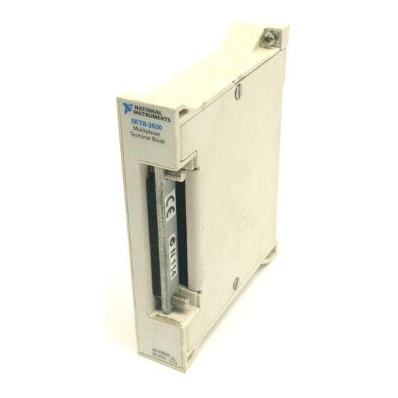
NI TB-2630
Terminal Block for the NI PXI-2530
Introduction
Conventions
»
This guide describes how to install and connect signals to the
National Instruments TB-2630 terminal block to configure your
NI PXI-2530 switch module as one of the following:
•
128 × 1 1-wire multiplexer
•
64 × 1 2-wire multiplexer
•
32 × 1 4-wire multiplexer
•
Eight 16 × 1 1-wire multiplexers
Refer to the NI Switches Getting Started Guide to determine when to install
the terminal block.
The TB-2630 terminal block installs in front of the PXI-2530 switch
module. The TB-2630 has ribbon cable headers to connect signals to the
switch. Screw terminals for the trigger input and trigger output signals also
are available.
The following conventions are used in this guide:
The » symbol leads you through nested menu items and dialog box options
to a final action. The sequence File»Page Setup»Options directs you to
pull down the File menu, select the Page Setup item, and select Options
from the last dialog box.
This icon denotes a note, which alerts you to important information.
Advertisement

Related Manuals for National Instruments NI TB-2630


Summary of Contents for National Instruments NI TB-2630
- Page 1 NI TB-2630 Terminal Block for the NI PXI-2530 This guide describes how to install and connect signals to the National Instruments TB-2630 terminal block to configure your NI PXI-2530 switch module as one of the following: • 128 × 1 1-wire multiplexer •...
-
Page 2: Unpack The Terminal Block
Notify NI if the terminal block appears damaged in any way. Do not install a damaged terminal block on a switch terminal block. Store the terminal block in the antistatic package when not in use. NI TB-2630 Installation Instructions ni.com... -
Page 3: Verify The Components
2. Verify the Components Make sure you have the following: ❑ NI TB-2630 terminal block ❑ PXI chassis ❑ NI PXI-2530 switch module ❑ 1/8 in. flathead screwdriver ❑ Eight 2 × 9, 0.100 in. pitch ribbon cable connectors (included) ❑... - Page 4 2 Strain-Relief Bar 8 Top Cover Screws 3 Ribbon Cable 9 Safety Ground Lug 4 Strain-Relief Screw 10 Ribbon Cable Connector 5 Chassis Screws 11 Ribbon Cable Header 6 Rear Connector Figure 1. TB-2630 Terminal Block NI TB-2630 Installation Instructions ni.com...
- Page 5 BANK 4 BANK 5 BANK 6 BANK 7 COM 4 COM 5 COM 6 COM 7 1WREF2 1WREF3 TRIGOUT TRIGIN USE SHIELDED CABLE ON TRIGGERS Figure 2. TB-2630 Terminal Block Signal Connections © National Instruments Corporation NI TB-2630 Installation Instructions...
- Page 6 BANK 7, PIN 1 ch27 BANK 1, PIN 12 ch70 BANK 4, PIN 7 ch113 BANK 7, PIN 2 ch28 BANK 1, PIN 13 ch71 BANK 4, PIN 8 ch114 BANK 7, PIN 3 NI TB-2630 Installation Instructions ni.com...
- Page 7 BANK 2, PIN 10 ch84 BANK 5, PIN 5 ch127 BANK 7, PIN 16 Note In the 128 × 1, 1-wire topology, 1WREF0 (BANK 0–1, PIN 17) is connected to COM1 (BANK 1, PIN 18). © National Instruments Corporation NI TB-2630 Installation Instructions...
- Page 8 BANK 2, PIN 12 BANK 3, PIN 12 ch60 BANK 6, PIN 13 BANK 7, PIN 13 ch28 BANK 2, PIN 13 BANK 3, PIN 13 ch61 BANK 6, PIN 14 BANK 7, PIN 14 NI TB-2630 Installation Instructions ni.com...
- Page 9 BANK 2, PIN 5 BANK 3, PIN 5 BANK 6, PIN 5 BANK 7, PIN 5 ch21 BANK 2, PIN 6 BANK 3, PIN 6 BANK 6, PIN 6 BANK 7, PIN 6 © National Instruments Corporation NI TB-2630 Installation Instructions...
-
Page 10: Install The Terminal Block
The NI PXI-2530 should already be installed in a PXI chassis. Plug the TB-2630 into the front connector of the PXI-2530. Tighten the top and bottom chassis screws on the back of the terminal block rear panel to hold it securely in place. NI TB-2630 Installation Instructions ni.com... - Page 11 Refer to Figure 4 for a diagram of a 0.100 in. pitch cable assembly with a 0.100 in. pitch connector and a 0.050 in. pitch ribbon cable. © National Instruments Corporation NI TB-2630 Installation Instructions...
-
Page 12: Compliance And Certifications
This product is designed to meet the requirements of the following standards of safety for electrical equipment for measurement, control, and laboratory use: • IEC 61010-1, EN 61010-1 • UL 3111-1, UL 61010B-1 • CAN/CSA C22.2 No. 1010.1 NI TB-2630 Installation Instructions ni.com... -
Page 13: Electromagnetic Compatibility
Refer to the Declaration of Conformity (DoC) for this product for any additional regulatory compliance information. To obtain the DoC for this product, visit , search by model number or product line, and click the ni.com/certification appropriate link in the Certification column. © National Instruments Corporation NI TB-2630 Installation Instructions... - Page 14 National Instruments, NI, ni.com, and LabVIEW are trademarks of National Instruments Corporation. Refer to the Terms of Use section on ni.com/legal for more information about National Instruments trademarks. Other product and company names mentioned herein are trademarks or trade names of their respective companies. For patents covering National Instruments products, refer to the appropriate location: Help»Patents in your software, the patents.txt file on your CD, or ni.com/patents.
- Page 15 取り付け手順 NI TB-2630 NI PXI-2530 用端子台 NI TB-2630 このガイドでは、 端子台の取り付けおよび信号の接続方法、 NI PXI-2530 および スイッチモジュールを次のいずれかに構成する方法を 説明します。 • × 単線式マルチプレクサ • × 線式マルチプレクサ • × 線式マルチプレクサ • 8 16 × 単線式マルチプレクサ 端子台を取り付ける順番については、 『 スイッチスタートアップガイ ド』を参照してください。 はじめに TB-2630 PXI-2530 端子台は、 スイッチモジュールの前面に取り付けます。 TB-2630 では、信号線とスイッチの接続にはリボンケーブルを使用しま...
- Page 16 太字 太字のテキストは、メニュー項目やダイアログボックスのオプションな ど、ソフトウェアで選択またはクリックする必要がある項目を表します。 また、太字のテキストは、パラメータ名も表します。 斜体 斜体のテキストは、変数、強調、または重要な概念の説明を示します。 ま た、入力する必要のある文字列や値を表すこともあります。 このフォントのテキストは、キーボードから入力する必要があるテキスト monospace や文字、コードの一部、プログラムサンプル、構文例を表します。 また、 ディスクドライブ、パス、ディレクトリ、プログラム、サブプログラム、 サブルーチンなどの名称、デバイス名、関数、操作、変数、ファイル名お よび拡張子の引用にも使用されます。 端子台を箱から取り出す 取り扱い中に端子台を破損しないために、以下の予防措置を行ってくださ い。 注意 露出しているコネクタピンには絶対に触れないでください。 • 接地ストラップを使用したり、接地されている物体に触れて、身体を 接地する。 • 静電気防止用パッケージをシャーシの金属部分に接触させてから、端 子台をパッケージから取り出す。 端子台を箱から取り出し、部品がゆるんでいないかどうか、また、破損箇 所がないかどうか調べます。 端子台が破損している場合は、ナショナルイ ンスツルメンツまでご連絡ください。 破損している端子台をスイッチモ ジュールに取り付けないでください。 端子台は、使用しないときは静電気防止用パッケージに入れて保管してく ださい。 NI TB-2630 ni.com/jp 取り付け手順...
- Page 17 × 0.100 in. 、 ピッチリボンケーブルコネクタ(同梱) ❑ 28 AWG 0.050 in. コンダクタ、 、 ピッチリボンケーブル(非同梱) 信号を接続する 信号を端子台に接続するには、次の手順に従います。 マイナスドライバーを使用して、端子台の上部カバーのネジを外しま す。 端子台から上部カバーを注意して取り外します。 ストレインリリーフアセンブリの つのネジを緩めてストレインリ リーフ上部のバーを取り外します。 4. 2 × リボンケーブルコネクタを、各 コンダクタリボンケーブルに 取り付けます。 各リボンケーブルをヘッダに接続します。 ストレインリリーフバーを元に戻して、ストレインリリーフアセンブ リの つのネジを締めてケーブルを固定します。 端子台の上部カバーを元のように取り付けます。 上部カバーのネジを締めて、端子台の上部カバーを固定します。 © National Instruments Corporation NI TB-2630 取り付け手順...
- Page 18 ストレインリリーフバー間の隙間 端子台の上部カバー ストレインリリーフバー 上部カバー用ネジ リボンケーブル 接地用圧着端子 ストレインリリーフ用ネジ リボンケーブルコネクタ シャーシ用ネジ リボンケーブルヘッダ 後部コネクタ 1 TB-2630 図 端子台 NI TB-2630 ni.com/jp 取り付け手順...
- Page 19 COM 0 COM 1 COM 2 COM 3 1WREF0 1WREF1 BANK 4 BANK 5 BANK 6 BANK 7 COM 4 COM 5 COM 6 COM 7 1WREF2 1WREF3 TRIGOUT TRIGIN 2 TB-2630 図 端子台の信号接続 © National Instruments Corporation NI TB-2630 取り付け手順...
- Page 20 BANK 4, PIN 8 ch114 BANK 7, PIN 3 ch29 BANK 1, PIN 14 ch72 BANK 4, PIN 9 ch115 BANK 7, PIN 4 ch30 BANK 1, PIN 15 ch73 BANK 4, PIN 10 ch116 BANK 7, PIN 5 NI TB-2630 ni.com/jp 取り付け手順...
- Page 21 BANK 7, PIN 15 ch41 BANK 2, PIN 10 ch84 BANK 5, PIN 5 ch127 BANK 7, PIN 16 1WREF0 BANK 0–1, PIN 17 COM1 × メモ 、単線式トポロジでは、 ( )が BANK 1, PIN 18 ( )に接続されています。 © National Instruments Corporation NI TB-2630 取り付け手順...
- Page 22 BANK 2, PIN 13 BANK 3, PIN 13 ch61 BANK 6, PIN 14 BANK 7, PIN 14 ch29 BANK 2, PIN 14 BANK 3, PIN 14 ch62 BANK 6, PIN 15 BANK 7, PIN 15 NI TB-2630 ni.com/jp 取り付け手順...
- Page 23 BANK 2, PIN 8 BANK 3, PIN 8 BANK 6, PIN 8 BANK 7, PIN 8 ch24 BANK 2, PIN 9 BANK 3, PIN 9 BANK 6, PIN 9 BANK 7, PIN 9 © National Instruments Corporation NI TB-2630 取り付け手順...
- Page 24 BANK 7, PIN 15 ch31 BANK 2, PIN 16 BANK 3, PIN 16 BANK 6, PIN 16 BANK 7, PIN 16 端子台を取り付ける TB-2630 PXI-2530 端子台を のフロントパネルに接続するには、次の手順 に従います。 NI PXI-2530 メモ が既に シャーシに取り付けられていることを前提とします。 TB-2630 PXI-2530 を のフロントコネクタに差し込みます。 端子台の後部パネル背面にある上下のシャーシ用ネジを締めて、端子 台をしっかりと固定します。 NI TB-2630 ni.com/jp 取り付け手順...
- Page 25 ピッチはコネクタピッチの半分になります。 たとえば、 0.05 in. 2.54 mm 0.1 in. ( )ピッチのリボンケーブルは、 ( )ピッチのコネ クタを使用します。 リボンケーブルコネクタのアセンブリは、通常コネク 2.54 mm 0.1 in. タのピッチで定義されます。 ( )ピッチコネクタの 2.54 mm 0.1 in. 1.27 mm ( )ピッチケーブルアセンブリおよび 0.05 in. ( )ピッチのリボンケーブルについては図 を参照してください。 © National Instruments Corporation NI TB-2630 取り付け手順...
- Page 26 ての詳細は、表 を参照してください。 4 TB-2630 表 対応の他社製アクセサリ アクセサリ 製造元 製品番号 Samtec IDD-09-HG 9 2.54 mm 0.1 in. × ( )ピッチリボンケーブルコネクタ Samtec 2.54 mm 0.1 in. IDSD-09 ( )ピッチケーブルコネクタアセンブリ シリーズ 2.54 mm 1.27 mm ( ピッチコネクタおよび ピッチリボン ケーブル) NI TB-2630 ni.com/jp 取り付け手順...
- Page 27 FCC Part 15 、 、および Class A ( )準拠 メモ に適合させるには、このデバイスをシールドケーブルと一緒に使用してく ださい。 適合 この製品は、以下のように、 マーク改正に基づいて、該当する 理 事会指令による基本的要件に適合しています。 ........73/23/EEC 低電圧指令(安全性) 電磁両立性 ............ 89/336/EEC 規格( ) メモ この製品のこのほかの適合規格については、この製品の適合宣言( ) を参照してください。 この製品の適合宣言を入手するには、 ni.com/ (英語)にアクセスして型番または製品ラインで検索し、該当 certification するリンクをクリックしてください。 © National Instruments Corporation NI TB-2630 取り付け手順...
- Page 28 National Instruments Corporation 、 、 、および は National Instruments (米国ナショナルインスツルメンツ社)の商標です。 の商標の詳細については、 Terms of Use ni.com/legal の「 」セクションを参照してください。本文書中に記載されたその他の National Instruments 製品名および企業名は、それぞれの企業の商標または商号です。 の製品を保護 する特許については、ソフトウェアに含まれている特許情報(ヘルプ→特許情報) 、 に含まれている patents.txt ファイル、または ni.com/patents のうち、該当するリソースから参照してください。 373684C-01 2007 年 月 © 2003–2007 National Instruments Corporation. All rights reserved...
Need help?
Do you have a question about the NI TB-2630 and is the answer not in the manual?
Questions and answers