
Related Manuals for Lissmac LMK 400 TFE

Summary of Contents for Lissmac LMK 400 TFE
- Page 1 OPERATING MANUAL MINI CRANE LMK 400 TFE LMK 400 TFE/DK LISSMAC Maschinenbau GmbH Lanzstrasse 4 D-88410 Bad Wurzach Phone +49 (0) 7564 / 307 - 0 Fax +49 (0) 7564 / 307 - 500 lissmac@lissmac.com www.lissmac.com 1/72...
- Page 2 2/72...
- Page 3 Legal information This operating manual is valid for: LISSMAC Mini crane LMK 400 TFE LMK 400 TFE/DK Head office: LISSMAC Maschinenbau GmbH Lanzstraße 4 D - 88410 Bad Wurzach Tel: +49 (0) 7564 / 307 – 0 Fax: +49 (0) 7564 / 307 – 500 lissmac@lissmac.com...
- Page 4 BASIC SAFETY INFORMATION Warnings and symbols used in this manual SIGNAL WORD Type and source of danger Consequence of non-compliance Action to avert the danger. The signal word under the hazard symbol indicates the level of danger. DANGER This signal word indicates an extremely dangerous situation. If the situation is not avoided, the consequence will be fatal injuries.
- Page 5 The following warnings and safety information has been applied to the machine. Observe the operating manual Wear hearing protection Sound power level (volume) of the machine Suspended loads hazard Falling parts hazard Overhead obstacle hazard Crushing hazard from above Crushing hazard from pivoting ballast or unintentional rolling of machine High voltage hazard Lashing point for crane transport Fixing point for the forklift...
- Page 6 OPERATING MANUAL Preface This operating manual is designed to make it easy to familiarize yourself with the machine and use it for its intended purpose. The operating manual contains important information on how to operate the machine safely, properly and economically.
-
Page 7: Table Of Contents
3.7. Traction drive unit (ONLY LMK 400 TFE/DK) ..............25 3.8. Trolley running gear (only LMK 400 TFE/DK) ..............26 3.9. Engage the rotary drive of the motor (only for LMK 400 TFE/DK) ........26 3.10. Setting up the tower ..................... 27 4. -
Page 8: Table Of Contents 1. Features & Benefits
1. FEATURES & BENEFITS Through intense cooperation with users, a practice-oriented mini crane was developed and approved by the TÜV. Professional processing and simple handling of the LISSMAC mini cranes increase safety and virtually eliminate operator error. Base frame, tower and jibs are completely hot-dip galvanized – no rust or paint damage – long- lived and robust for the toughest use ... -
Page 9: Principle Of Intended Use
Use in accordance with the operating manual! In particular, faults which may adversely affect its safety must be rectified immediately. The LISSMAC Mini crane LMK is part of the device class of the manually controlled load manipulating Intended use devices and is used exclusively to move building bricks only in conjunction with a tested LISSMAC brick gripper. -
Page 10: Organizational Action
1.2. Organizational action This operating manual must be kept within easy reach for everybody at the place of use. Supplements to the operating manual include general statutory and other binding regulations for preventing accidents and protecting the environment and must be obeyed. These duties may also relate, for example, to handling hazardous substances or wearing personal protective equipment or road traffic regulations. -
Page 11: Safety Information During The Various Operating Phases
Work on the electrical equipment on the machine may only be carried out by a qualified electrician or by trained personnel under the management and supervision of a qualified electrician and in compliance with the electronic regulations. Only allow personnel being trained, instructed or those completing an apprenticeship to work on the machine under the constant supervision of an experienced person. -
Page 12: Operation
The jib and the ballast must move freely within the radius of action. Persons and/or materials may not remain in this area. The LISSMAC mini crane remains stable even if it is overloaded. The chain hoist is adjusted to the maximum permissible load-bearing capacity, with regard to safety. -
Page 13: Information About Special Types Of Dangers
Always re-tighten screw connections after maintenance and repair work! If safety equipment has to be removed for setting, maintenance and repair work, the safety equipment must be re-installed and tested immediately after completing the maintenance and repair work! 1.5. Information about special types of dangers 1.5.1. -
Page 14: Packaging And Bearing
Do not start the machine if it is damaged. Damaged cables and plug connectors also pose a safety risk and must not be used. In this case, please inform LISSMAC Maschinenbau GmbH. If the machine is not to be started straight away after being on impact, it must be protected from moisture and dirt. -
Page 15: Device Description
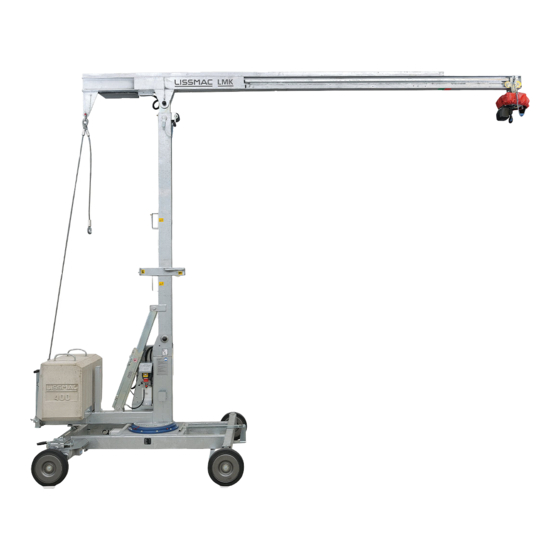
2. DEVICE DESCRIPTION The LISSMAC mini crane is a mobile lifting aid that can be quickly set up. The application possibilities can be determined by the gripping devices due to its compact design. The mini crane proves itself in day-to-day use on construction sites due to the highest processing quality and due to its precise handling. - Page 16 16/72...
-
Page 17: Designation Of Machine Parts
2.1. Designation of machine parts Item 1 Chassis Item 20 Socket pins – Support tube (lower bore) Item 2 Traction drive unit Item 21 Switch Item 3 Ballast Item 22 Plug-Hydraulic power unit Item 4 Swivel frame Item 23 Socket pins – Support tube (upper bore) Item 5 Hydraulic power unit Item 24... -
Page 18: Technical Data
2.3. Technical Data LMK 400 TFE LMK 400 TFE/DK Dimensions (LxWxH) 6100 x 2100 x 5210 mm (Telescoped 6710 mm) Transport dimensions LxWxH 6100 x 2100 x 2000 mm Lifting capacity 400 kg Hock height 5000 mm Hook height 4500/6000 mm... -
Page 19: Sound Power Level
2.4. Sound power level WARNING Noise hazard Ear protection must be worn, if the sound power level exceeds 85 dB (A). Wear your personal ear protection. The specification defines the volume of the noise emissions related to the workplace of the operator and the sound power level of the machine. -
Page 20: Commissioning
The hydraulic power unit is filled with hydraulic oil by the manufacturer. Only use hydraulic oil approved by Hydraulic oil the manufacturer. In order to put the LISSMAC mini crane in operation, a reliable power source with RCCB-switch must be Electricity available. Operating voltage is 400 V protected with 16 A fuse. -
Page 21: Parking Brake
3.3. Parking brake WARNING Unintended change in position of the machine Danger of injuries due to unintended change in position of the machine. The parking brake must be used to secure the mini crane against rolling away unintentionally. releasing and closing of the parking brake is performed by: ... -
Page 22: Ballast Support And Handle
3.4. Ballast support and handle DANGER Crushing hazard from a toppling mini crane If the mini crane is not balanced correctly it may tip over and causer serious personal and property damage. The ballast support must be lowered for stability with every assembly and dismantling. ... -
Page 23: Swivel Lock
3.5. Swivel lock WARNING Crushing hazard by swiveling machine parts Danger of injuries from rotating machine parts of the machine. The swivel lock must be engaged under the ballast to ensure that the mini crane cannot swivel unintentionally. Engage the swivel lock ... -
Page 24: Telescoping Of The Tower
3.6. Telescoping of the tower DANGER Crushing hazard from a toppling mini crane If the mini crane is not balanced correctly it may tip over and causer serious personal and property damage. The ballast support must be lowered for stability with every assembly and dismantling. ... -
Page 25: Traction Drive Unit (Only Lmk 400 Tfe/Dk)
3.7. Traction drive unit (ONLY LMK 400 TFE/DK) DANGER Danger of serious injuries due to swiveling load on the mini crane The traction drive unit may only be activated if no load is attached on the chain hoist. The displacement in assembled state and with suspended load is prohibited. -
Page 26: Trolley Running Gear (Only Lmk 400 Tfe/Dk)
Mount the trolley running gear Tighten the clamping lever (Item 1) 3.9. Engage the rotary drive of the motor (only for LMK 400 TFE/DK) The motor must be engaged into the internal gear rim. Turn the jib slightly until the motor is engaged. -
Page 27: Setting Up The Tower
3.10. Setting up the tower WARNING Non-instructed personnel Injury due to incorrect operation Any work on/with the mini crane must be carried out by trained personnel Observe the safety regulations Order all other personnel to leave the working area. Cordon off the working area if necessary. ... -
Page 28: Transport
4. TRANSPORT 4.1. Transport position WARNING Suspended loads Risk of injury from falling parts Do not enter/remain in the area below suspended loads! Use only lifting and loading equipment with adequate load capacity and length The centre of gravity of the machine is located off-centre ... -
Page 29: Transport Possibilities
4.2. Transport possibilities WARNING Heavy loads Injury from falling parts Do not enter/remain in the area below suspended loads! Do not leave loads on the mini crane unattended! Use only lifting and loading equipment with adequate load capacity and length ... -
Page 30: Relocation With Building Crane When Assembled
4.3. Relocation with building crane when assembled NOTICE Only models with trolley drive (model code DK) should be lifted by crane in the erected position. The trolley cannot be secured on the hand-guided models with the crane in the erect position. The gripper tool and control panel may therefore swing and slide uncontrollably during the lifting process and cause personal and property damage. -
Page 31: Operation
5. OPERATION NOTICE The principle of the intended use must be observed! No displacement with suspended load. No lifting without engaged parking brake. No pulling or lifting of loads at an angle. Do not drive over electric supply cables. Keep safe distance to overhead power lines. In case of a nearing thunderstorm, disassemble and unplug crane. -
Page 32: Radio Control
5.3. Radio control Item 1 Turn the jib Item 7 Chassis forward Item 2 Turn the jib Item 8 Chassis backward Item 3 Lower the load Item 9 Controller On Item 4 Lift the load Item 10 Controller Off Item 5 Trolley forward Item 11 Actuation chassis forward/backward... -
Page 33: Mounting The Ehs Controller
For intended use, the controller must be mounted on the brick gripper! The cable must not wrap around the chain. Example for a LISSMAC brick gripper with mounted transmitter holder + controller 5.5. EHS-Controller For intended use, the controller must be mounted on the brick gripper! -
Page 34: Connecting The Ehs-Controller (Optional)
5.5.1. Connecting the EHS-Controller (Optional) Optional only for LMK TFE / DK Item 1 On/Off main switch Item 2 Connection torque motor Item 3 Connection cable carrier Item 4 Connection power lead Item 5 Connection receiver radio remote control In order to use the EHS-controller, the plugs of Item 3 and Item 4 must be connected with each other. - Page 35 The manual control unit must be connected via the adapter assembly (42pin to 10pin) at the chain hoist motor housing (left connection) underneath the protective cover. Models without rotary drive do not require an adapter assembly. 35/72...
-
Page 36: Disassembly
6. DISASSEMBLY 6.1. Disassembly DANGER Crushing hazard from a toppling mini crane If the mini crane is not balanced correctly it may tip over and causer serious personal and property damage. The ballast support must be lowered for stability with every assembly and dismantling. ... -
Page 37: Reset Telescoping
6.2. Reset telescoping DANGER Crushing hazard from a toppling mini crane If the mini crane is not balanced correctly it may tip over and causer serious personal and property damage. The ballast support must be lowered for stability with every assembly and dismantling. ... -
Page 38: Maintenance
7. MAINTENANCE 7.1. Servicing DANGER High voltage hazard Severe or fatal injuries from electric shock Maintenance and repair work may only be carried out by trained personnel. The mains plug must be removed from the power supply before starting any maintenance or repair ... -
Page 39: Lube Points
7.2. Lube points The lube points must be lubricated according to the specified intervals The manufacturer uses the grease “Energrease LS2 BP“. Weekly Monthly Annually Grease the lubricating nipples Slewing ring Trolley Wheels on the chassis ... -
Page 40: Troubleshooting
7.4. Troubleshooting The mains plug must be removed from the power supply before starting any maintenance or repair work! Action must be taken to ensure that the machine cannot be switched on again by others accidentally. Maintenance and service work may only be carried out by trained personnel. Error Possible cause Remedy... -
Page 41: Regular Inspection (Maintenance Book)
8. REGULAR INSPECTION (MAINTENANCE BOOK) The mini crane must be checked by a qualified inspector after the first commissioning at intervals within a maximum period of one year. The inspection plate is located on the nameplate on the frame of the mini crane and indicates the next inspection date to be carried out by an expert. -
Page 42: Check Measurement
8.1. Check measurement r = 272 All types of canes must be tested by a qualified inspector every four years, as well as in the 14th and 16th year of operation and then annually (employer’s liability insurance association, TÜV, certified SGS-body, etc.). A check measurement must be carried out every 12 months at the latest after the specified procedure. -
Page 43: Maintenance Schedule
8.2. Maintenance schedule This section is designed to keep a record of maintenance work already completed and as a service record. All maintenance and service work must be entered to create a full record. Machine/Type: Serial number/Year of manufacture: Date Completed maintenance or service work Date/Signature 43/72... -
Page 44: Warranty
9. WARRANTY The warranty period for this machine is 12 months. A warranty is only provided for the following wearing parts if the wear is not caused by normal operation. Wearing parts are parts which are designed to wear during operating when the machine is used for its intended purpose. -
Page 45: Hydraulic Plan
10. HYDRAULIC PLAN LMK = 0.7 mm P = 240 bar P = 0.37 kW n = 1450 min-1 45/72... -
Page 46: Spare Parts Lmk 400
Lever for locking LMK 300473 Cylinder head screw with Allen DIN 912 6x35 201552 Compression spring VD 215 622610 Bolt 211416 LISSMAC-Handle PVC No. 83/20 690466 Brake LMK 201452 Brake plate LMK 300 680759 Strain relief LMK 400289 Grommet DA... - Page 47 300361 Clamping pin ISO 8748 6x16 Spiral 95+96 623271 Washer 201391 Rubber spring 691028 Crank 211416 LISSMAC-Handle PVC No. 83/20 220006 Spring cotter pin 5,0x110 mm Galvan. 200324 Chain C. Link 0.208 m 691026 Socket pin 202754 Guide rail made of PA...
- Page 48 622063 Quick release axle 680238 Socket pins complete LMK 691644 LMK Adjustable part 202620 Ballast type 1070 kg concrete only for LMK 400 TFE + LMK 400 TFE/DK 201968 Guy cable 5470 mm D=16 mm 690830 152.1 623267 Guard LMK/TFE...
- Page 49 49/72...
-
Page 50: Spare Parts Lmk 400 Tfe/Dk
12. SPARE PARTS LMK 400 TFE/DK Article- Spare part LMK 400 Item Description Specification Piece recommendation TFE/DK 690452 Chassis 622584 Locking pin 300555 Hex-head screw DIN 439 20x1.5 622027 Threaded block 400702 Switch 400400 Cable 1.2 m 691035 Locking strip... - Page 51 Article- Spare part LMK 400 Item Description Specification Piece recommendation TFE/DK 300842 Hex-head screw 300842 Hex-head screw 613273 Spacer tube 1005631 Holder 300127 Securing screw SK 10x40 Verbus 300263 Washer-Steel DIN 7349 10.5 300146 Hex-head screw DIN 934 10.0 62.1+.2+.3 1010719 Housing 63.1 + .2...
- Page 52 Locking nut BIW V-shape 10.0 Galvan. 201350 Cylindrical rubber metal buffer 1035646 Radio remote control receiver LISSMAC ECO / FSE 312 and transmitter 1059370 Radio remote control receiver LISSMAC ECO / FSE 312 1059371 Radio transmitter LISSMAC ECO / FSE 312...
- Page 53 Spare part LMK 400 Item Article-No. Description Specification Piece recommendation TFE/DK 1011508 Power lead COMPLETE 1011353 Female insert 1011352 Socket housing 400059 CE connector 400 V 400135 Rubber cable 1011509 Cable/Travel motor COMPLETE 1011355 Pin insert 10 poles 1011494 Sleeve housing 460606 Cable gland 400401...
- Page 54 54/72...
- Page 55 55/72...
- Page 56 56/72...
- Page 57 EHS4-S6 Pos. Art.-Nr. Deutsch English 201797 Klebeschild Adhesive plate 691099 Gehäuse Housing 360212 Sechskantschraube Hexagon screw 301219 Scheibe PA 10.5 Washer PA 10.5 622256 Handgriff Hand grip 211416 Handgriff Gummi Rubber Hand grip 622497 Deckel Cover 300438 Innensechskantschraube M6x16 Allen screw M6x16 300289 Scheibe 6,4 vz Washer 6,4 galv...
- Page 58 The technical documentation is archived by LISSMAC Maschinenbau GmbH, Lanzstrasse 4, D-88410 Bad Wurzach. The LISSMAC Mini crane LMK is part of the device class of the manually controlled load Description of the manipulating devices and is used exclusively to move building bricks only in conjunction with a machine tested LISSMAC brick gripper.
-
Page 59: Circuit Diagram
CIRCUIT DIAGRAM 59/72... - Page 60 60/72...
- Page 61 61/72...
- Page 62 62/72...
- Page 63 63/72...
- Page 64 64/72...
- Page 65 65/72...
- Page 66 66/72...
- Page 67 67/72...
- Page 68 68/72...
- Page 69 69/72...
- Page 70 70/72...
- Page 71 71/72...
- Page 72 72/72...
Need help?
Do you have a question about the LMK 400 TFE and is the answer not in the manual?
Questions and answers