
Related Manuals for BEKA BR323AL


Summary of Contents for BEKA BR323AL
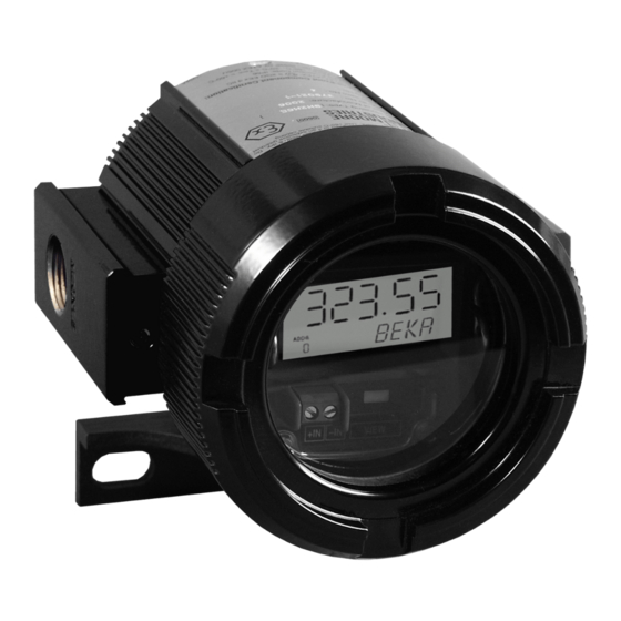
- Page 1 BR323AL and BR323SS Flameproof Loop powered field mounting indicators Issue 3 Issue: July 2008...
- Page 2 6.4 Linear calibration Appendix 2 6.5 Non-linear calibration CSA Approval for use in Canada 6.6 Square root extraction The BR323AL and BR323SS are CE marked to show compliance with the European Explosive Atmospheres Directive 94/9/EC and the European EMC Directive 89/336/EEC...
- Page 3 5 digit indicators indicators are configured and calibrated by which display the current flowing in a 4/20mA BEKA software running on a PC connected via a loop in engineering units. The instruments only temporary serial data link, the indicators introduce a 2.3V drop allowing them to be...
- Page 4 Zones, gas groups and T rating will only persist for a short Group II, Category 2G, Ex d IIC T6 certification period. allows the BR323AL and BR323SS indicators to be installed in: Be used with dusts having a Minimum Ignition Temperature of:...
- Page 5 ½ inch NPT (N suffix on product number). Fig 4 illustrates a typical application in which a BR323AL or BR323SS indicator is connected in series with a 2-wire transmitter and calibrated to display the measured variable or control signal in engineering units.
-
Page 6: Installation
The appropriate model BR323AL or BR323SS rotating anticlockwise. should be chosen depending on the severity of the environment. The BR323AL is housed in an b. Remove the BR323 electronic assembly epoxy painted aluminium enclosure and the from the enclosure by gently squeezing the BR323SS in a stainless steel enclosure suitable retaining clip and pulling –... - Page 7 Using a battery powered 4/20mA calibrator or a battery powered laptop WARNING computer will avoid earth loop problems. The temporary serial data link must NOT be connected to a BR323AL or BR323SS indicator when an explosive atmosphere is present. The BR323 electronic assembly...
- Page 8 Fig 7 BEKA Configuration Programme Screen 6.4 Linear calibration With the indicator connected to the PC as shown in Fig 6 and communication established, (5) Display Resolution proceed as follows: Defines the number of digits displayed by the indicator after the decimal point. None,...
- Page 9 BR323 should have the required curve. display. The calibration information may be stored or printed from the PC in the normal way. Fig 8 Non-linear BEKA Configuration Programme display screen...
- Page 10 (3) Enter the required indicator display 6.7 Other non-linear curves Type the required BR323 indicator Zero and Other non-linear curves may be generated by Full scale displays into the appropriate entering the number of breakpoints required and panels. Clicking the Upload button will manually keying the required x and y values into the table.
-
Page 11: Maintenance
There should be 2.3V explosive atmosphere is not present. wiring between the +ve & -ve terminals. If a BR323AL or BR323SS fails after it has been No display Incorrect Check that a current functioning correctly, the following procedure and no volts... - Page 12 8. ACCESSORIES 8.1 Pipe mounting kit The pipe mounting kit comprises a stainless steel ‘U’ bolt that enables the BR323AL and BR323SS indicators to be mounted onto any pipe with an outside diameter up to 50mm. 8.2 Tag strip...
- Page 13 FM approval for use in the USA CSA approval for use in Canada A1.1 Factory Mutual Approval CAUTION For installations in the USA, the BR323AL and BR323SS have explosion proof FM Approval. Copies of the Certificate of Compliance are The CSA Approval only applies to the...
Need help?
Do you have a question about the BR323AL and is the answer not in the manual?
Questions and answers