
Related Manuals for BEKA BA358E


Summary of Contents for BEKA BA358E
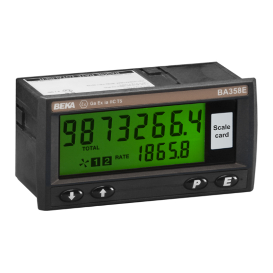
- Page 1 BA358E Intrinsically safe 4/20mA loop-powered panel mounting Rate Totaliser Issue 6 Issue: 6 April 2016...
-
Page 2: Table Of Contents
6.18 Security code 6.19 Reset to factory defaults Appendix 2 6.20 Over-range IECEx certification Appendix 2 FM and cFM certification The BA358E is CE marked to show compliance with the European Explosive Atmospheres Directive 94/9/EC and the European EMC Directive 2004/108/EC... -
Page 3: Description
1. DESCRIPTION If the 4/20mA current is disconnected during The BA358E is a panel mounting intrinsically safe operation the latest total and grand total are stored 4/20mA loop-powered Rate Totaliser primarily in permanent memory. intended for use with flowmeters. The instrument... - Page 4 Totaliser will display the time in hours, 2.2 Displays minutes seconds since The BA358E has two digital displays and instrument was powered or the total associated annunciators, plus a flow indicator as display was reset. The elapsed time is shown on page 1.
-
Page 5: Intrinsic Safety Certification
EN 60079-11 for simple apparatus. This simplifies the application and intrinsic safety documentation Be used with gases in groups: for a loop into which the BA358E is connected. Group A propane Apart from Ci, the affect of the Rate Totaliser may... -
Page 6: Reset Terminals
3.5 Reset terminals 3.6 Certification label information The BA358E total display may be reset to zero by The certification label is fitted in a recess on the connecting the reset terminals RS1 and RS2 top outer surface of the instrument enclosure. It together. -
Page 7: System Design For Hazardous Areas
4. SYSTEM DESIGN FOR HAZARDOUS AREA 4.2 Resetting the total display to zero The BA358E total display may be reset to zero by 4.1 Flow transmitter loops momentarily connecting the reset terminals RS1 A BA358E Rate Totaliser may be connected in... - Page 8 Fig 3a Simplest circuit with one side of 20mA current loop connected to earth. Also illustrates resetting from safe area. Fig 3b Two Zener barrier channels are required if the 4/20mA current loop can't be earthed at the barrier busbar. Also shows optional resetting from hazardous area Fig 3c Galvanic isolator can be used with any...
-
Page 9: Installation
5. INSTALLATION 5.2 EMC 5.1 Location The BA358E Rate Totaliser complies with the The BA358E Rate Toyslider has a robust glass requirements of the European EMC Directive reinforced modified enclosure with 2004/108/EC. For specified immunity all wiring toughened glass window. The front of the Rate... -
Page 10: Installation Procedure
Fig 6. specified in Fig 4. Thus the scale card can easily be changed without removing the BA358E Rate Totaliser from the b. Slide the gasket over the body of the Rate panel or opening the instrument enclosure. -
Page 11: Configuration And Calibration
6. CONFIGURATION AND CALIBRATION second, per minute or per hour. The total scaling The BA358E is configured and calibrated via the factor '5CALE-t' is a wide range configurable four front panel push buttons that are located dividing factor allowing the rate and total displays below the display. -
Page 12: Summary Of Configuration Functions
6.2 Accessing the configuration and 6.3 Summary of configuration functions calibrations functions. This section summarises each of the main Throughout this manual push buttons are shown configuration functions and includes a cross as P, E, ▼ or ▲, and legends displayed by the reference to a more detailed description. -
Page 13: Clear Grand Total
Display Summary of function Display Summary of function 'CAL' Calibration of the rate display ‘5CALE-t’ Total scale factor using an external current source. Defines the arithmetic relationship Enables the zero and span of the between the rate and total displays. rate display to be adjusted using an May be adjusted between 0.0001 external current source such as a... - Page 14 Display Summary of function 'r5Et' Reset Rate Totaliser to factory defaults. Contains two sub-functions, Select: ‘ConF’ Returns instrument to default configuration shown in section 6.2 ‘LtAb’ Returns lineariser to defaults shown in section 7.5 Both instructions must be confirmed by entering ‘5urE’ digit by digit before they will be executed.
- Page 16 6.4 Rate Totaliser function: ‘FunC’ ‘bi-Lin’ 16 segment adjustable lineariser This configuration function defines the relationship May be adjusted to compensate for between the Rate Totaliser’s 4/20mA input current flowmeter non-linearity with bi-directional and the instruments’s rate display. Three flow. Use of the lineariser is described in alternatives are available for uni-direction flow and section 7 of this instruction manual.
- Page 17 'ZEro' prompt . after it, or it may be omitted. Pressing the ▲ button will cause the BA358E to Notes: display 'SPAn' which is a request for a 20mA input a.
- Page 18 4/20mA input current, or to disconnect the briefly displaying ‘Gt CLrd’ to confirm that the BA358E Rate Totaliser from the 4/20mA loop. instruction has been performed and return the instrument 'CLr.Gtot'...
-
Page 19: Clip Off
When enabled, ‘t-rE5Et’ allows an operator to reset flashing. The value of the flashing digit may be the BA358E total display to zero by operating the changed by pressing the ▼ or ▲ button. When ▼ and ▲ push buttons simultaneously for at least this digit is set as required pressing P will transfer two seconds. -
Page 20: Security Code
When enabled, ‘Gt-rE5Et’ allows an operator to To reset the Rate Totaliser or lineariser select reset the BA358E grand total to zero by operating ‘r5Et’ from the configuration menu and press P, the the E and ▲ push buttons simultaneously for at Rate Totaliser will display one of the reset options least ten seconds. -
Page 21: Lineariser
7. LINEARISER 7.1 Lineariser calibration using an external A sixteen segment, seventeen break-point (0 to 16) current source. lineariser may be selected in the ‘FunC’ section of This method allows direct calibration of the the configuration menu. The position of each lineariser with an external current source and is the break-point is fully adjustable so that the slope of preferred method when traceability is required. -
Page 23: Example, Adding Break-Points To A New Rate Totaliser
The delete break-point sub-function 'dEL' operates before the default break-point '1:1' which will result in exactly the same way as the 'Add' sub-function in a display of '1:2'. If more new break-points are described above. Once within the ‘dEL’ sub- required, using the ▲... -
Page 24: Example, Adding Break-Points To A New Rate Totaliser
To add a break-point using the ▲ or ▼ button the required rate display at the first break-point. select 'SEt' from the configuration menu and press When set as required, press E to return to the ‘0:n’ P which will result in the 'Add' sub-function prompt prompt from which the next break-point can be being displayed. -
Page 25: Calibration Examples
'1' and return to the 'rE5n' 20mA at a flow of 1100 litres / minute. prompt in the configuration menu by BA358E is required to display flow in litres per pressing E. minute with a resolution of 1 litre and total flow in cubic metres with a resolution of 0.1 cubic metres. - Page 26 In this example the rate display is in using an external current source 'CAL' litres per minute but the total display is from the configuration menu and press required in cubic metres: The BA358E will request a 4mA 5CALE-t Units of rate display input by displaying 'ZEro'.
-
Page 27: Using The Internal Reference
100% of maximum flow. A security code of 1209 is required. In the operating mode the BA358E is required to display the input current as a percentage of span when the P push-button is operated and operating the ▼ and ▲ buttons... -
Page 28: Maintenance
We recommend that initially instrument equipment should be used unless a gas calibration should be checked annually. clearance certificate is available. If a BA358E fails after it has been functioning correctly, the following table may help to identify the cause of the failure. -
Page 29: Guarantee
10.1 Scale card condition when designing an alarm system. The BA358E Rate Totaliser has a window on the Fig 11 illustrates the conditions available and right hand side of the display through which a scale shows which are fail safe. -
Page 30: Solid State Output
10.3.1 Solid state output Each alarm has a galvanically isolated single pole solid state switch output as shown in Fig 12. The output is polarised and current will only flow in one direction. less than 5Ω + 0.7V Roff greater than 1MΩ Fig 12 Equivalent circuit of each alarm output 10.3.2 Intrinsic safety Each alarm output is a separate galvanically... -
Page 32: Configuration And Adjustment
10.3.3 Configuration and adjustment Summary of alarm configuration functions When optional alarms are fitted to a BA358E Rate Totaliser the configuration menu is extended as Display Description of function shown in Fig 13. The additional functions appear between the ‘C- - P’ and ‘5CALE-t’ functions. For 'EnbL’... - Page 33 The flashing digit of the setpoint can be adjusted using the ▲ e.g. A BA358E calibrated to display a rate of 0 to and ▼ push buttons, and the P button to move 10000, with a high alarm set at 9000 and control to the next digit.
-
Page 34: Access Setpoint
e.g. A Rate Totaliser with a high alarm set at 9000 reference, ‘ALr1’ or ‘ALr2’ when the alarm output is and an alarm delay of 30 seconds will perform as activated. If both alarm outputs are activated by follows: one variable, the display alternates between the numerical value and ‘Alr1-2’. -
Page 35: Adjusting Alarm Setpoints From Display Mode
10.3.14 Adjusting alarm setpoints from the which the other setpoint may be selected, or the display mode. Rate Totaliser may be returned to the display Access to the alarm setpoints from the Rate mode by pressing E again. Totaliser display mode is obtained by operating the P and ▲... -
Page 36: Display Backlight
10.4 Display backlight described in sections 3 and 4 of this manual The BA358E loop powered Rate Totaliser can be remain valid with the backlight loop powered. supplied with a factory fitted backlight that may be loop or separately powered. -
Page 37: Appendix 1
Temperature equipment should be used. The BA358E has been ATEX certified as Group II, Category 1D Ex ia IIIC T80ºC Da IP20 apparatus, All models have IP66 front of panel protection and Ta -40 to 70°C. - Page 38 IP6X protection. The gasket supplied to seal the joint between the indicator and the mounting panel should be used and the BA358E should be secured with four panel mounting clamps. Note: These...
-
Page 39: Appendix 2
The gasket supplied to seal the joint between the indicator and the mounting panel should be used Ex ia IIC T5 Ga and the BA358E should be secured with four panel Ex ia IIIC T80ºC Da mounting clamps. Ta = -40ºC to 70ºC... -
Page 40: Appendix 3
Appendix 3 A3.2 Nonincendive approval FM Approval for use in the USA and The BA358E Rate Totaliser is also approved to cFM Approval for use in Canada nonincendive standard FM Class 3611 allowing installation in Division 2 hazardous (classified) A3.0 Factory Mutual Approval...
Need help?
Do you have a question about the BA358E and is the answer not in the manual?
Questions and answers