HEIDENHAIN IK 5000 QUADRA-CHEK Quick Reference Manual
Hide thumbs
Also See for IK 5000 QUADRA-CHEK:
- Operating instructions manual (409 pages) ,
- Installation instructions manual (173 pages) ,
- Installation instruction (98 pages)

Related Manuals for HEIDENHAIN IK 5000 QUADRA-CHEK

Summary of Contents for HEIDENHAIN IK 5000 QUADRA-CHEK
- Page 1 Quick Reference Guide Guide de Démarrage rapide IK 5000 QUADRA-CHEK Software Version 3.0.x 9/2013...
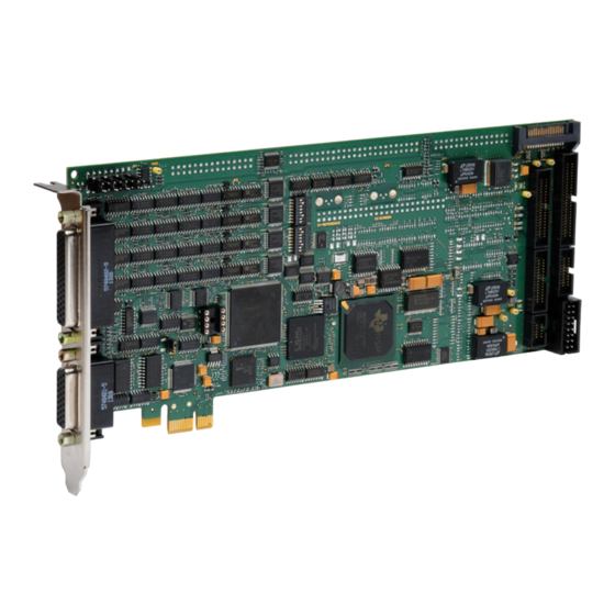
- Page 2 IK 5000 QUADRA-CHEK Card, flyout and connector configurations IK 5294 IK 5294 Metrology Computer 1 Vpp/ 540550-40 1 Vpp) X, Y, Z 540550-10 TTL) Axis encoders 1 Vpp/ and foot switch 44 pin edge 1 Vpp/ 681041-02 (Foot switch) 540541-24...
-
Page 3: Installation And Setup
IK 5000 QUADRA-CHEK English Installation and Setup Very important Please note For detailed description, see www.heidenhain.de For your information Before Power up Using this Guide IK 5000 connectors are shown in the diagrams of preceding pages. Connector This guide includes installation and... -
Page 4: Software Setup
IK 5000 systems. Please refer to the IK 5000 OEM Setup Guide Caution at www.heidenhain.de for details Attach antistatic protection such as a regarding all setup parameters for the Flyout cable connection to IK 5000 foot strap or wristband before installing standard IK 5000 product family. - Page 5 Installation and Setup 4. Launch IK 5000 Encoder Setup • To limit stage travel, click the LIMIT • When a few full limit-to-limit motions Click START/PROGRAMS/QC5000/ SWITCH SETUP BUTTON. The have been completed without scale ENCODER SETUP . The Custom Encoder Limit Switch Setup screen will be errors, click the OK BUTTON to return Setup screen will be displayed.
- Page 6 11. Set radix type IK 5000. Click TOOLS/OPTIONS/ • If you are prompted, call Heidenhain Note A repeatable machine zero can be set PASSWORD=oem to set the radix to a customer support with the System utilizing encoder reference marks or period or comma.
- Page 7 OEM Setup screen Refer to the IK 5000 OEM Setup Guide Optical Edge Included at www.heidenhain.de for detailed Follow these instructions if your system • Enter a character into the Password explanations and instructions. includes optical edge detection.
- Page 8 DIAMETER and enter any other be performed if desired. Please refer desired parameters. to the IK 5000 OEM Setup Guide 6. Calibrate auto focus at www.heidenhain.de for detailed • If your system includes auto focus, 2. Qualify probe tip instructions. click PROBE/PROBE LIBRARY/AUTO •...
-
Page 9: Installation Et Configuration
IK 5000 QUADRA-CHEK Français Installation et Configuration Très important Remarques Pour une description détaillée, voir www.heidenhain.fr Pour information Avant la mise sous tension Utilisation de ce guide Les connecteurs IK 5000 figurent dans les diagrammes de la page précédente. Ce guide contient les instructions Le repérage de la connectique se trouve... -
Page 10: Configuration Du Logiciel
à utiliser le système standard IK 5000. Référez 1. Déconnecter l'alimentation du PC vous au guide de configuration OEM IK 5000 à www.heidenhain.fr pour des 2. Ouvrir le boitier du PC détails concernant les paramètres de Enlever les couvercles ou panneaux configuration de la famille des produits pour avoir accès aux slots d'extension... - Page 11 Installation et Configuration 3. Installation du logiciel IK 5000 • Pour limiter la vitesse, introduire des Insérer le CD IK 5000 dans le lecteur faibles valeurs pour chaque axe dans Remarque de CD ROM et suivez les instructions les champs SPEED : Les imperfections des signaux affichées dans l'écran pour installer le •...
- Page 12 • Si vous y êtes invités, appelez le les butées fixes pour les compensations 11. Initialiser le type de base support client HEIDENHAIN avec d'erreurs SLEC, NLEC et 3D. Les Cliquez sur OUTILS/OPTIONS/MOT DE votre numéro ID système. Un mot de marques de référence sont requises...
- Page 13 Reportez vous rence ou les fins de course. Cliquez au Manuel de configuration OEM sur OUTILS/OPTIONS CNC/ORIgINE IK 5000 à www.heidenhain.fr pour des AUTOMATIQUE pour afficher les instructions détaillées. paramètres d'origine automatique. 4. Configurer les paramètres du •...
- Page 14 • Sélectionnez un grossissement dans au Manuel de configuration OEM sur PALPEUR/PALPEUR CONTACT/ le tableau du haut, cliquez sur le IK 5000 à www.heidenhain.de pour SéLECTEUR PALPEUR. L'écran de BOUTON ETALONNER et suivez les des instructions détaillées. la position du bout du palpeur est instructions affichées à...
- Page 15 Card, flyout and connector configurations IK 5293 IK 5293 Metrology Computer 1 Vpp/ 540550-40 1 Vpp) X, Y, Z 540550-10 TTL) Axis encoders 1 Vpp/ and foot switch 44 pin edge 1 Vpp/ 681041-02 IK 5293 Card (Foot switch) Touch probe on request Touch probe 50 pin header...
- Page 16 Card, flyout and connector configurations IK 5394-EG IK 5394-EG Metrology Computer 1 Vpp/ 540550-40 1 Vpp) X, Y, Z 540550-10 TTL) Axis encoders 1 Vpp/ and foot switch 44 pin edge 1 Vpp/ 681041-02 (Foot switch) 540541-24 1 Vpp) Q Axis 540541-05 TTL) Encoder...
- Page 17 Card, flyout and connector configurations IK 5394-3D IK 5394-3D Metrology Computer 1 Vpp/ 540550-40 1 Vpp) X, Y, Z 540550-10 TTL) 1 Vpp/ Axis encoders and foot switch 44 pin edge 1 Vpp/ 681041-02 (Foot switch) 1 Vpp) 540541-24 Q Axis TTL) 540541-05 Encoder...
- Page 18 Card, flyout and connector configurations IK 5493 IK 5493 Metrology Computer 1 Vpp/ 540540-24 1 Vpp) X, Y 540540-05 TTL) Axis encoders 1 Vpp/ and foot switch 44 pin edge 681041-02 (Foot switch) 681045-01 (Stepper) 681046-01 (Servo) X, Y Axis X,Y Axis 540660-56 CNC control...
- Page 19 Card, flyout and connector configurations IK 5494-2D IK 5494-2D Metrology Computer 1 Vpp/ 1 Vpp) 540550-40 X, Y, Z TTL) 540550-10 1 Vpp/ Axis encoders and foot switch 44 pin edge 1 Vpp/ 681041-02 681045-02 (Stepper) (Foot switch) 681046-02 (Servo) X, Y, Z Axis XYZ Axis 540660-56...
- Page 20 Card, flyout and connector configurations IK 5494-3D IK 5494-3D Metrology Computer 1 Vpp/ 540550-40 1 Vpp) X, Y, Z 540550-10 TTL) 1 Vpp/ Axis encoders and foot switch 44 pin edge 1 Vpp/ 681041-02 681045-02 (Stepper) (Foot switch) 681046-02 (Servo) X, Y, Z Axis XYZ Axis 540660-56...
- Page 21 Card, flyout and connector configurations IK 5594 IK 5594 Metrology Computer 1 Vpp/ 540550-40 1 Vpp) X, Y, Z 540550-10 TTL) 1 Vpp/ Axis encoders and foot switch 44 pin edge 1 Vpp/ 681041-02 681045-02 (Stepper) (Foot switch) 681046-02 (Servo) X, Y, Z Axis XYZ Axis 540660-56...
- Page 22 IK 5000 QUADRA-CHEK PC Card and Flyout Connectors IK 5294 IK 5293 IK 5394-EG Crosshairs Manual Touch Probe Manual Optical Edge IK 5394-3D IK 5493 Manual Touch Probe with Video Edge Optical Edge with CNC IK 5494-2D IK 5494-3D Video Edge with CNC...
- Page 23 IK 5000 QUADRA-CHEK IK 5294 Crosshair 2D System IK 5293 Touch Probe 2D/3D System IK 5394-3D Video/Touch Probe 3D System IK 5494-2D Video Evaluation 2D System with CNC IK 5494-3D Video/Touch Probe 2D/3D System with CNC IK 5394-EG Optical Edge Detector 2D System...
- Page 24 IK 5594 Video/TP-200 Touch Probe 2D/3D System with CNC Tolerancing ISO 8015 ISO 2768 - m H < 6 mm: ±0.2 mm...
- Page 25 X, Y, Z Encoder axes and Footswitch IK 5294, IK 5293, IK 5394-EG, IK 5394-3D, IK 5494-2D, IK 5494-3D, IK 5594 X, Y Encoder axes and Footswitch IK 5493 X, 0° + X, 90° + X, Ref mark + X, -12 Vdc Y, 0°...
- Page 26 Q Encoder axis IK 5294 IK 5394-EG IK 5394-3D IK 5493 IK 5494-2D IK 5494-3D IK 5594 Q, 0° + Q, 90° + Q, Ref mark + Q, -12 Vdc Q, +12 Vdc Q, 0° - Q, 90° - Q, Ref mark - Q, Reset Q, +12 Vdc Q, +5 Vdc...
- Page 27 Touch probe IK 5394-3D IK 5494-3D LED+ LED- TP-200 Touch probe IK 5594 STOP PPOFF STOP + 5 Vdc PDAMP LEDOFF Zoom motor IK 5394-3D IK 5494-2D IK 5494-3D IK 5594 TTL out 11 TTL out 10 TTL out 9 TTL out 8 TTL out 7 TTL out 6...
- Page 28 83301 Traunreut, Germany { +49 8669 31-0 | +49 8669 5061 E-mail: info@heidenhain.de Vollständige und weitere Adressen siehe www.heidenhain.de www.heidenhain.de For complete and further addresses see www.heidenhain.de HEIDENHAIN Vertrieb Deutschland FARRESA ELECTRONICA S.A. 83301 Traunreut, Deutschland 08028 Barcelona, Spain 02-384 Warszawa, Poland ...
Need help?
Do you have a question about the IK 5000 QUADRA-CHEK and is the answer not in the manual?
Questions and answers