Cognex In-Sight 2800 Series Reference Manual
Hide thumbs
Also See for In-Sight 2800 Series:
- Quick reference manual (40 pages) ,
- Quick reference manual (38 pages)
Table of Contents
Advertisement
Advertisement
Table of Contents

Related Manuals for Cognex In-Sight 2800 Series


Summary of Contents for Cognex In-Sight 2800 Series
- Page 1 ® In-Sight 2800 Series Reference Manual 2022 April 26 Revision: 22.1.1.127...
-
Page 2: Legal Notices
Copyright © 2022. Cognex Corporation. All Rights Reserved. Portions of the hardware and software provided by Cognex may be covered by one or more U.S. and foreign patents, as well as pending U.S. and foreign patents listed on the Cognex web site at: cognex.com/patents. -
Page 3: Symbols
Symbols Symbols The following symbols indicate safety precautions and supplemental information: WARNING: This symbol indicates a hazard that could cause death, serious personal injury or electrical shock. CAUTION: This symbol indicates a hazard that could result in property damage. Note: This symbol indicates additional information about a subject. Tip: This symbol indicates suggestions and shortcuts that might not otherwise be apparent. -
Page 4: Table Of Contents
Connecting the Power and I/O Breakout Cable Indicator LEDs Using Your In-Sight Vision System Installing In-Sight Vision Suite Trigger Types Industrial Protocols Specifications In-Sight 2800 Series Vision System In-Sight 2800 Series Vision System Image Sensor LED and Laser Wavelengths Acquisition Trigger Input... - Page 5 Table of Contents High-Speed Outputs High Speed Output Wiring Ethernet Cable Power and I/O Breakout Cable Specifications CCB-PWRIO-05 Cleaning and Maintenance Clean the Housing Clean the Vision System Image Sensor Window Clean the Vision System Lens Cover Regulations and Conformity 中...
-
Page 6: Getting Started
Getting Started Getting Started This section provides general information about the In-Sight 2800 series vision system and the accessories and systems. About the In-Sight 2800 Series The In-Sight 2800 series vision systems are high-performance, easy hardware and software setup vision systems that... -
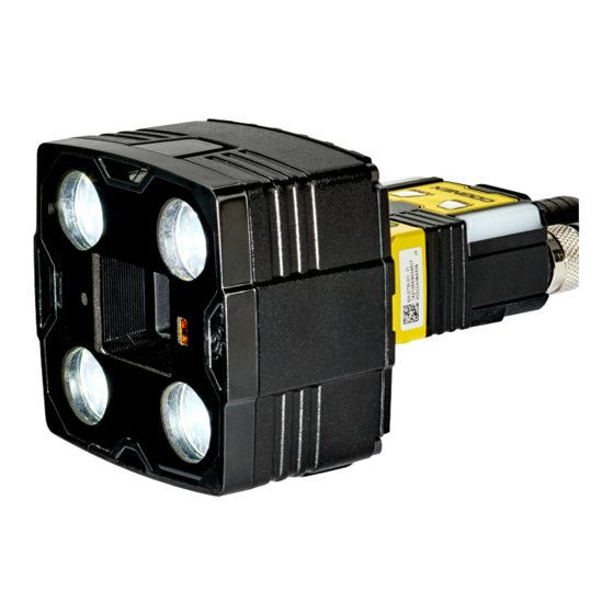
Page 7: Illumination Options For In-Sight 2800
Illumination Options for In-Sight 2800 The following illumination options are available for In-Sight 2800 vision systems: Multi Torch: The Multi Torch is a high-powered integrated multi-color light module with RED, GREEN, BLUE, and WHITE colors in a single package. The Multi Torch is compatible with vision system using 12 or 16 mm lens. High Powered Illumination for 16 mm lens: High-powered integrated light attachments are available in RED or WHITE color options for In-Sight 2800 Mini vision systems using a 16 mm lens. -
Page 8: Accessories
Accessories You can purchase the following components separately. For a list of options and accessories, contact your local Cognex sales representative. Lenses Accessory Product Number Illustration 12mm Manual Focus Lens Module to be used with Multi Torch light 280-TORCH-MAN12 16mm Manual Focus Lens Module to be used with Multi Torch light 280-TORCH-MAN16 Blue bandpass filter supported with IS2800 Mini with 6.2mm lens illumination only... -
Page 10: Lens Covers
Lens Covers Accessory Product Number Illustration Front cover. Use with a 6.2 mm lens only. DM280-CVR-62 Polarized front cover. Use with a 6.2 mm lens only. DM260-LENS-62CVR-F Extended front cover. Use with a 16 mm lens only. DM260-LENS-16CVR Extended front cover, half-polarized. Use with a 16 mm lens only. DM260-LENS-16CVR-P Extended front cover, fully-polarized. -
Page 11: Mounting Brackets
Mounting Brackets Accessory Product Number Illustration Universal mounting bracket DM100-UBRK-000 Pivot mounting bracket DM100-PIVOTM-01 Flat surface mounting plate adapter for Multi-Torch configuration 280-BKT-ADAPT... -
Page 12: Cables
I/O Extension Cable CKR-200-CBL-EXT Support Many information resources are available to help you use the vision system: The EasyBuilder Help file, provided with the In-Sight software. On-demand training: cognex.com/on-demand-training.aspx. The In-Sight online support site: cognex.com/support/insight. Note: For the latest documentation, visit: support.cognex.com/documentation/in-sight. -
Page 13: Setting Up Your In-Sight Vision System
Read this section to learn how the vision system connects to its standard components and accessories. Note: Cables are sold separately. If a standard component is missing or damaged, immediately contact your Cognex Authorized Service Provider (ASP) or Cognex Technical Support. CAUTION: All cable connectors are keyed to fit the connectors on the vision system. -
Page 14: Dimensions
Setting Up Your In-Sight Vision System Dimensions The following sections list dimensions of the vision system. Note: Dimensions are in millimeters and are for reference purposes only. All specifications are for reference purposes only and can change without notice. In-Sight 2800 Mini with 6.2 mm lens The following image shows the dimensions of In-Sight 2800, equipped with 6.2 mm lens. -
Page 15: In-Sight 2800 Mini With 16 Mm Lens
In-Sight 2800 Mini with 16 mm Lens The following image shows the dimensions of In-Sight 2800 equipped with 16 mm lens. -
Page 16: In-Sight 2800 With Multi Torch
In-Sight 2800 with Multi Torch The following image shows the dimensions of In-Sight 2800 equipped with Multi Torch. -
Page 17: In-Sight 2800 Mini With 6.2 Mm Lens - Right Angle Configuration
In-Sight 2800 Mini with 6.2 mm Lens - Right Angle Configuration The following image shows the dimensions of In-Sight 2800 equipped with L-shaped extension and 6.2 mm lens. -
Page 18: In-Sight 2800 Mini With 16 Mm Lens - Right Angle Configuration
In-Sight 2800 Mini with 16 mm Lens - Right Angle Configuration The following image shows the dimensions of In-Sight 2800 equipped with L-shaped extension and 16 mm lens. -
Page 19: In-Sight 2800 With Multi Torch - Right Angle Configuration
In-Sight 2800 with Multi Torch - Right Angle Configuration The following image shows the dimensions of In-Sight 2800 equipped with L-Shaped extension and Multi Torch. -
Page 20: Field Of View And Working Distance
Field of View and Working Distance This section discusses the Field of View values for the IS2800 with Multi Torch and IS2800 Mini configurations. (On the diagrams, the values at the top are in mm and the values at the bottom of the top values in the brackets are in inch). In-Sight 2800 with Multi Torch and 12 mm Lens Working Distance Horizontal FOV... -
Page 21: In-Sight 2800 With Multi Torch And 16 Mm Lens
In-Sight 2800 with Multi Torch and 16 mm lens Working Distance Horizontal FOV Vertical FOV Minimum 50 mm (1.97 in) 12.6 mm (0.5 in) 9.45 mm (0.37 in) Midpoint 300 mm (11.8 in) 75.6 mm (2.98 in) 56.7 mm (2.23 in) Maximum 500 mm (19.69 in) 126 mm (4.96 in) -
Page 22: In-Sight 2800 Mini With 6.2 Mm Lens
In-Sight 2800 Mini with 6.2 mm Lens Working Distance Horizontal FOV Vertical FOV Minimum 50 mm (1.97 in) 65 mm (2.56 in) 48.7 mm (1.92 in) Midpoint 300 mm (11.8 in) 195.1 mm (7.68 in) 146.3 mm (5.76 in) Maximum 500 mm (19.69 in) 325 mm (12.8 in) 243.8 mm (9.60 in) -
Page 23: In-Sight 2800 Mini With 16 Mm Lens
In-Sight 2800 Mini with 16 mm Lens Working Distance Horizontal FOV Vertical FOV Minimum 100 mm (3.94 in) 25.2 mm (1 in) 18.9 mm (0.74 in) Midpoint 300 mm (11.8 in) 75.6 mm (2.98 in) 56.7 mm (2.23 in) Maximum 500 mm (19.69 in) 126 mm (4.96 in) 94.5 mm (3.72 in) -
Page 24: Installing And Changing Lenses
Installing and Changing Lenses This section provides an overview about installing and changing different kinds of lenses. Installing Manual Lens on Multi Torch on page 24 Changing Front Cover on Multi Torch on page 30 Note: Use a Phillips screwdriver with drive size #1 for all Phillips screws that are reachable from the front side. Note: Disconnect the vision system from power before changing lenses or mounts. - Page 25 Note: Make sure that the gasket is still present and flat between the adapter and the engine housing.
- Page 26 2. Install the manual lens subassembly to the unit. a. Push the six pins into the designated holes of the adapter and align the cylindrical flange to the center of the unit. b. Tighten the the M2 x 5 mm HSH screw halfway, then tighten the M2 x 12 mm HSH screw halfway as well. Continue screwing each screw incrementally, until tightening them to 0.4 Nm, using a torque wrench.
- Page 27 Note: Make sure that the gear teeth mesh properly and that the contact pads are clean (free of dust and grease).
- Page 28 3. Screw in the four screws from the adapter into the back of the light module housing. Note: Observing the tightening sequence below, tighten all four M2.5 x 13 mm HSH screws to 0.25 Nm using a torque wrench.
- Page 29 4. Screw in the four screws from the light module into the front cover. Note: Observing the tightening sequence below, tighten all four M2.5 x 34 mm HSH screws to 0.25 Nm using a torque wrench.
-
Page 30: Changing Front Cover On Multi Torch
Changing Front Cover on Multi Torch 1. Unscrew the four screws from the light module, then take off the front cover from the light module. - Page 31 2. Attach the new front cover and screw in the four screws into the front cover. Note: Observing the tightening sequence below, tighten all four M2.5 x 34 mm HSH screws to 0.25 Nm using a torque wrench.
-
Page 32: Connecting The Vision System
Connecting the Vision System Mounting the Vision System on page 33 Connecting the Ethernet Cable on page 34 Connecting the Power and I/O Breakout Cable on page 35... -
Page 33: Mounting The Vision System
Mounting the Vision System The vision system provides mounting holes for attachment to a mounting surface. CAUTION: The vision system has to be grounded, either by mounting the vision system to a fixture that is electrically grounded or by attaching a wire from the vision system’s mounting fixture to frame ground or Earth ground. -
Page 34: Connecting The Ethernet Cable
Connecting the Ethernet Cable CAUTION: The Ethernet cable shield has to be grounded at the far end. Whatever this cable is plugged into (typically a switch or router) should have a grounded Ethernet connector. A digital voltmeter has to be used to validate the grounding. -
Page 35: Connecting The Power And I/O Breakout Cable
Connecting the Power and I/O Breakout Cable CAUTION: To reduce emissions, connect the far end of the Breakout cable shield to frame ground. Note: Perform wiring or adjustments to I/O devices when the vision system is not receiving power. You can clip unused wires short or use a tie made of non-conductive material to tie them back. Keep bare wires separated from the +24VDC wire. -
Page 36: Using Your In-Sight Vision System
Follow the steps below to install and connect your vision system to the In-Sight Vision Suite. 1. Download the latest version of In-Sight Vision Suite from support.cognex.com/ and follow the on-screen steps. 2. Connect the 2800 series vision system to your PC. -
Page 37: Trigger Types
Using Your In-Sight Vision System Trigger Types The In-Sight 2800 vision systems support the following trigger modes. Self: At a time interval you configure, the vision system acquires an image and runs the job on said image automatically. Single (external trigger): Acquires a single image and runs the current job on the acquired image. The vision system relies on an external trigger source. -
Page 38: Industrial Protocols
Using Your In-Sight Vision System Industrial Protocols The vision system supports the following industrial protocols: EtherNet/IP™, EDS and PLC PROFINET (Class B) SLMP Protocol TCP/IP OPC/UA For more information see Industrial Communications in In-Sight documentation. -
Page 39: Specifications
0 (Trigger), 1, 2, : ≥ ± 12 V : 4.2 mA @ 24 V Ethernet 10/100/1000. Full duplex or half duplex. Job Storage 7.8 GB In-Sight 2800 Series Vision System Image Sensor Specification Model 1/3-inch CMOS, global shutter Image Sensor... - Page 40 Specifications Specification Model Diagonal size: 6.17 mm Image Sensor Properties Pixel size: 2.8 μm Image Resolution (pixels) 1440 x 1080 (1.6mp) 720x540 (SVGA) Minimum exposure: 29 μs Electronic Shutter Speed Maximum exposure: 10 ms (with internal illumination) Maximum exposure: 200 ms (with external illumination) Image Acquisition at Full Resolution Up to 45 Hz Multi Torch: Lens Type...
-
Page 41: Led And Laser Wavelengths
Specifications LED and Laser Wavelengths The following table shows LED types and the related peak wavelengths. Model Wavelength In-Sight 2800 Mini with 6.2mm Lens Illumination/with 16mm White Chromaticity coordinates acc. to CIE 1931 • Lens and High Powered Illumination Cx 0.34 (typ.) • Cy 0.33 (typ.) Blue 465 nm 617 nm... -
Page 42: High-Speed Outputs
Specifications High-Speed Outputs Specification Description : 26 VDC through external load Voltages : ≤ ± 3 V @ 50 mA Current : 50 mA maximum sink or source current Each line is protected against over-current, short circuits and transients from switching inductive loads. High current inductive loads require an external protection diode. -
Page 43: High Speed Output Wiring
Specifications High Speed Output Wiring To connect to an NPN-compatible PLC input, connect one of the vision system's high-speed outputs directly to the PLC input. When enabled, the output pulls the PLC input down to less than 3 VDC. To connect to a PNP-compatible PLC input, connect one of the vision system's high-speed outputs directly to the PLC input. -
Page 44: Ethernet Cable
Specifications Ethernet Cable The Ethernet cable provides Ethernet connectivity to the vision system. The Ethernet cable is used to connect the vision system to other network devices. P1 Pin Number Wire Color Signal Name P2 Pin Number White/Orange TxRx A + Orange TxRx A - White/Green... -
Page 45: Ccb-Pwrio-05
Specifications CCB-PWRIO-05 The Power and I/O Breakout cable provides access to trigger and high-speed outputs. For RS-232, use the Power Supply return path for ground. The figure on the left shows the plug on the device. Pin# Signal Names Wire Color Out 2/In 2 Yellow White/Yellow... -
Page 46: Cleaning And Maintenance
Cleaning and Maintenance Cleaning and Maintenance Clean the Housing To clean the outside of the vision system housing, use a small amount of mild detergent cleaner or isopropyl alcohol on a cleaning cloth. Do not pour the cleaner on the vision system housing. CAUTION: Do not attempt to clean any In-Sight product with harsh or corrosive solvents, including lye, methyl ethyl ketone (MEK) or gasoline. -
Page 47: Regulations And Conformity
Regulations and Conformity Regulations and Conformity Note: For the most current CE declaration and regulatory conformity information, see the Cognex support site: cognex.com/support. In-Sight vision systems have Regulatory Model numbers 50208, 50210, 50215, 50216 and meet or exceed the requirements of all applicable standards organizations for safe operation. However, as with any electrical equipment, the best way to ensure safe operation is to operate them according to the agency guidelines that follow. -
Page 48: 中 国 大 陆 Rohs (Information For China Rohs Compliance)
表示用于本部件的至少一种均质材料中所含的危害物质超过GB / T26572 - 2011 的限制要求。 For European Community Users Cognex complies with Directive 2012/19/EU OF THE EUROPEAN PARLIAMENT AND OF THE COUNCIL of 4 July 2012 on waste electrical and electronic equipment (WEEE). This product has required the extraction and use of natural resources for its production. It may contain hazardous substances that could impact health and the environment, if not properly disposed. - Page 49 Copyright © 2022 Cognex Corporation. All Rights Reserved.
Need help?
Do you have a question about the In-Sight 2800 Series and is the answer not in the manual?
Questions and answers