
Related Manuals for turck TBEN-L5-4RFID-8DXPOPC-UA


Summary of Contents for turck TBEN-L5-4RFID-8DXPOPC-UA
- Page 1 Your Global Automation Partner TBEN-L5-4RFID-8DXP- OPC-UA Compact RFID Interface Instructions for Use...
- Page 2 Hans Turck GmbH & Co. KG | T +49 208 4952-0 | F +49 208 4952-264 | more@turck.com | www.turck.com...
-
Page 3: Table Of Contents
Feedback about these instructions................ 8 Notes on the product......................... 9 Product identification..................... 9 Scope of delivery ...................... 9 Legal requirements...................... 9 Turck service........................ 9 Exclusion of liability ...................... 9 For your safety .......................... 10 Intended use........................ 10 General safety notes ..................... 10 Notes on Ex protection.................... 10 Ex approval requirements for use in Ex area............ 10... - Page 4 Executing the ScanStart method by setting the ScanActive variables ...... 92 HF applications – using the ScanStart method in HF bus mode ...... 93 Hans Turck GmbH & Co. KG | T +49 208 4952-0 | F +49 208 4952-264 | more@turck.com | www.turck.com...
- Page 5 Carry out a firmware update via the web server (from firmware version 2.0.11.0)........................ 111 12 Repair.............................. 113 12.1 Returning devices....................... 113 13 Disposal ............................ 113 14 Technical data .......................... 114 15 Appendix: approvals and markings.................... 117 16 Turck subsidiaries – contact information................... 118 V02.00 | 2021/11...
- Page 6 Contents Hans Turck GmbH & Co. KG | T +49 208 4952-0 | F +49 208 4952-264 | more@turck.com | www.turck.com...
-
Page 7: About These Instructions
This symbol denotes actions that the user must carry out. RESULTS OF ACTION This symbol denotes relevant results of actions. Other documents Besides this document, the following material can be found on the Internet at www.turck.com: Data sheet Instructions for use Declarations of conformity (current versions) -
Page 8: Feedback About These Instructions
If you have any suggestions for improving the design or if some information is missing in the document, please send your suggestions to techdoc@turck.com. Hans Turck GmbH & Co. KG | T +49 208 4952-0 | F +49 208 4952-264 | more@turck.com | www.turck.com... -
Page 9: Notes On The Product
Only a functioning IT security concept can ensure the security of the data for the entire installa- tion in which the device is used. Turck does not accept any liability in the event that third parties access data transferred with the device. -
Page 10: For Your Safety
Do not install the device in areas critically exposed to UV light. Prevent risks caused by electrostatic charge. Protect unused connectors with dummy plugs to ensure protection class IP67. Hans Turck GmbH & Co. KG | T +49 208 4952-0 | F +49 208 4952-264 | more@turck.com | www.turck.com... -
Page 11: Notes On Ul Approval
Notes on UL approval Use UL certified PVVA or CYJV cables that are suitable for the current/voltage rating and have an insulation temperature of at least 90 °C. V02.00 | 2021/11... -
Page 12: Product Description
Eight universal digital channels as 2 A PNP inputs and/or outputs Multiple LEDs for status display Integrated Ethernet switch enables line topology 10 Mbps/100 Mbps transfer rate Hans Turck GmbH & Co. KG | T +49 208 4952-0 | F +49 208 4952-264 | more@turck.com | www.turck.com... -
Page 13: Operating Principle
A specific OPC UA client can be programmed with the OPC UA Stack of the OPC Foundation. It is also possible to use the OPC UA SDKs of other manufacturers. Turck recommends the use of the “.NET based OPC UA client/server SDK”. The OPC Foundation provides an overview of the available clients. -
Page 14: Rfid Commands (Methods)
WriteTag KillTag (only UHF) LockTag SetTagPassword WriteTagID Methods and functions in HF bus mode: ActivateBusHead DeactivateBusHead DeactivateAllBusHeads GetActivatedBusHeads GetConnectedBusHeadAddresses SetBusHeadAddress Hans Turck GmbH & Co. KG | T +49 208 4952-0 | F +49 208 4952-264 | more@turck.com | www.turck.com... -
Page 15: Hf Bus Mode
A tool is provided at www.turck.com/hf-busmodus for calculating the power. Every connected read/write head supplies a “ Tag present” signal in HF bus mode. HF bus mode is suitable for static applications and very slow dynamic applications because a com- mand can only be processed by one read/write head at a time. -
Page 16: Universal Digital Channels - Functions
Accessories for mounting, connecting and parameterizing can be found in product database under www.turck.com. The accessories are not part of the scope of delivery. Hans Turck GmbH & Co. KG | T +49 208 4952-0 | F +49 208 4952-264 | more@turck.com | www.turck.com... -
Page 17: Installing
Installing Installing the device in Zone 2 and Zone 22 In Zone 2 and Zone 22, the devices can be used in conjunction with the protective housing set . DANGER Potentially explosive atmosphere Risk of explosion through spark ignition For use in Zone 2 and Zone 22: „... -
Page 18: Mounting Onto A Mounting Plate
„ To avoid material abrasion and color changes: Protect the device from direct sunlight, e.g. by using protective shields. Hans Turck GmbH & Co. KG | T +49 208 4952-0 | F +49 208 4952-264 | more@turck.com | www.turck.com... -
Page 19: Grounding The Device
Grounding the device 5.4.1 Equivalent wiring diagram and shielding concept 4 x 15 nF 1 nF 1 nF 2,2 MΩ 2,2 MΩ Fig. 5: TBEN-L5-4RFID-8DXP-OPC-UA – equival- ent wiring diagram and shielding concept 5.4.2 Shielding of the fieldbus and I/O level The fieldbus and the I/O level of the modules can be grounded separately. -
Page 20: Disconnecting The Direct Grounding Of The Fieldbus Level: Removing The Grounding Clip
With mounted grounding clip: The shielding of the fieldbus and the module grounding are connected to the reference potential of the installation. Hans Turck GmbH & Co. KG | T +49 208 4952-0 | F +49 208 4952-264 | more@turck.com | www.turck.com... -
Page 21: Connection
Connection NOTICE Intrusion of liquids or foreign bodies through leaking connections Loss of protection class IP65/IP67/IP69K, device damage possible „ Tighten M12 connectors with a tightening torque of 0.6 Nm. „ Tighten 7/8” connectors with a tightening torque of 0.8 Nm. „... -
Page 22: Connecting The Power Supply
PWR LED changes from green to red. If V1 goes below the permissible minimum, the PWR LED goes out. Hans Turck GmbH & Co. KG | T +49 208 4952-0 | F +49 208 4952-264 | more@turck.com | www.turck.com... -
Page 23: Connecting Rfid Read/Write Devices
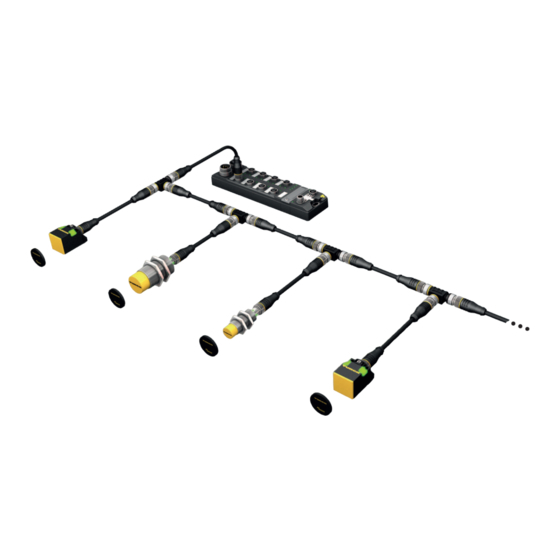
The user must determine by means of a power consumption analysis whether an additional power supply is required for the connected read/write heads (see information in the data sheet or tool at www.turck.com/hf-busmodus). The maximum permissible length of the bus is 50 m. - Page 24 RFID connection cable (e.g. RK4.5T-0.3-RS4.5T/S2503) TBEN-L…-4RFID-8DXP-… VT2-FKM5-FKM5-FSM5 TN-M30-H1147/C53 TN-M18-H1147/C53 up to 32 per port TN-CK40-H1147/C53 Fig. 18: HF bus mode setup Hans Turck GmbH & Co. KG | T +49 208 4952-0 | F +49 208 4952-264 | more@turck.com | www.turck.com...
- Page 25 Connecting read/write heads for HF bus mode in the Ex area NOTE Information on the maximum cable lengths in the Ex area is provided in the data sheets of the connected read/write heads. The following accessories are required for bus mode in the Ex area: TN-R42TC-EX/C53 read/write heads (ID 100020167) TN-R42TC-EX/C65 read/write head (ID 100028462) with integrated bus terminating resistor …/S2500 RFID connection cables...
- Page 26 Connection Connecting RFID read/write devices Fig. 19: System setup Hans Turck GmbH & Co. KG | T +49 208 4952-0 | F +49 208 4952-264 | more@turck.com | www.turck.com...
-
Page 27: Connecting Digital Sensors And Actuators
Connecting digital sensors and actuators The device has four 5-pin M12 male connectors for connecting digital sensors and actuators. The maximum tightening torque is 0.6 Nm. Fig. 20: M12 male connectors for connecting digital sensors and actuators „ Connect the sensors and actuators to the device as per the pin assignment below. „... -
Page 28: Commissioning
Turck Service Tool, FDT/DTM or via a web server. The settings are saved in the non- volatile memory of the device. Hans Turck GmbH & Co. KG | T +49 208 4952-0 | F +49 208 4952-264 | more@turck.com | www.turck.com... - Page 29 DHCP requests until it is assigned a fixed IP address. The DHCP client is automatically deactivated as soon as an IP address is assigned to the device via the DTM, the Turck Service Tool or a web server. Factory reset...
-
Page 30: Adjusting The Network Settings Via The Turck Service Tool
Click the required device. „ Click Change or press [F2]. NOTE Clicking the IP address of the device opens the web server. Hans Turck GmbH & Co. KG | T +49 208 4952-0 | F +49 208 4952-264 | more@turck.com | www.turck.com... - Page 31 „ Change the IP address and if necessary the network mask and gateway. „ Accept the changes by clicking Set in device. Fig. 26: Turck Service Tool – changing the device configuration V02.00 | 2021/11...
-
Page 32: Adjusting Network Settings Via The Web Server
Write the new IP address, subnet mask and default gateway via SET NETWORK CONFIG- URATION to the device. Fig. 27: Adjusting network settings via the web server Hans Turck GmbH & Co. KG | T +49 208 4952-0 | F +49 208 4952-264 | more@turck.com | www.turck.com... -
Page 33: Preparing The Device For Commissioning Via The Web Server
Opening the web server and editing the settings The web server can be opened via a web browser or via the Turck Service Tool. Calling the web server via the Turck Service Tool is described in the section ”Setting the Network address”. - Page 34 Unauthorized access to sensitive data „ Change the password after the first login. Turck recommends the use of a secure password. Hans Turck GmbH & Co. KG | T +49 208 4952-0 | F +49 208 4952-264 | more@turck.com | www.turck.com...
- Page 35 Ò „ Parameter OPC UA: enter the password in the OPC UA root password field. „ Click AUTHENTICATE. Fig. 30: Entering the OPC UA root password The parameters for the OPC UA configuration are shown. Fig. 31: Parameters for the OPC UA configuration V02.00 | 2021/11...
- Page 36 Preparing the device for commissioning via the web server The root password can be changed via Access data. Fig. 32: Changing the root password Hans Turck GmbH & Co. KG | T +49 208 4952-0 | F +49 208 4952-264 | more@turck.com | www.turck.com...
-
Page 37: Establishing The Connection Between The Opc Ua Server And Opc Ua Client
7.2.2 Establishing the connection between the OPC UA server and OPC UA client The following example uses UAExpert as the OPC UA client. „ Add the OPC UA server in the OPC UA client used. Fig. 33: Adding OPC UA server in the OPC UA client (example: UAExpert) „... - Page 38 The connection between the OPC UA server and OPC UA client is established and the Address Space in the client is created. Hans Turck GmbH & Co. KG | T +49 208 4952-0 | F +49 208 4952-264 | more@turck.com | www.turck.com...
- Page 39 Fig. 37: Connection established, address space created V02.00 | 2021/11...
-
Page 40: Validating Security Certificates
Fig. 38: Trusting security certificates The Trusted certificates area lists the trusted certificates and can be rejected by clicking REJECT. Fig. 39: Rejecting a certificate Hans Turck GmbH & Co. KG | T +49 208 4952-0 | F +49 208 4952-264 | more@turck.com | www.turck.com... - Page 41 Creating a specific security certificate The user can create a specific security certificate via Update own server certificate. The OPC UA clients must accept the new generated certificate. During the generation, the current IP address and host name are automatically added to the certificate. The certificate can also be edited via an OPC UA client if the highest security level is activated.
-
Page 42: Adapting Settings For Opc Ua Communication - Set Endpoints
If Anonymous is activated, a connection is allowed without a user login. Fig. 41: Setting security levels for SecurityPolicies Hans Turck GmbH & Co. KG | T +49 208 4952-0 | F +49 208 4952-264 | more@turck.com | www.turck.com... - Page 43 Issuing authorizations The users (Anonymous, root, singleUser, user1, user2) can be assigned different rights at Para- Ò meter User roles. Observer: authorized to search, read and receive events Operator: authorized to search, read, write and receive events and call up methods Engineer: authorized to search, read and configure safety-related parameters and methods (e.g.
- Page 44 The following settings can be changed in the Parameter OPC UA Server configuration area: Port Host name Name of the OPC UA server Fig. 43: Server configuration Hans Turck GmbH & Co. KG | T +49 208 4952-0 | F +49 208 4952-264 | more@turck.com | www.turck.com...
- Page 45 Changing the name resolution on the OPC UA server endpoint – choose NodeName for endpoint resolution In order to identify the endpoint uniquely, the OPC UA client checks the host name for the spe- cified IP address. Identification problems can occur if DHCP and DNS are not available in a net- work.
- Page 46 Language of the OPC UA Server. German and English are the available languages. Fig. 45: Changing language settings of the OPC UA server Hans Turck GmbH & Co. KG | T +49 208 4952-0 | F +49 208 4952-264 | more@turck.com | www.turck.com...
-
Page 47: Setting The Opc Ua Password
To access OPC UA parameters, enter the OPC UA root password. The default password is “Turck”. NOTICE Insufficiently secured devices Unauthorized access to sensitive data „ Change the password after the first login. Turck recommends the use of a secure password. Ò „ Parameter OPC UA: enter the password in the OPC UA root password field. - Page 48 90, DIP switch [MODE] at position 1) without entering a password. All other pos- sibilities to fully reset to the default settings, including the OPC UA passwords, are blocked. Hans Turck GmbH & Co. KG | T +49 208 4952-0 | F +49 208 4952-264 | more@turck.com | www.turck.com...
-
Page 49: Setting Up An Opc Ua Client Via An Sdk
7.2.6 Setting up an OPC UA client via an SDK The OPC UA client must be set up in order to connect the OPC UA server of the device to an OPC UA client. The following software is required for the setup: Client SDK, e.g. -
Page 50: Setting
In the information model the devices are defined as objects and structured as follows: Fig. 48: Information model of the RFID channel Ident 0 – example: UA Expert Hans Turck GmbH & Co. KG | T +49 208 4952-0 | F +49 208 4952-264 | more@turck.com | www.turck.com... - Page 51 Fig. 49: Information model of DXP channels 8 and 9 – example: UA Expert V02.00 | 2021/11...
-
Page 52: Rfid Channels - Mapping In The Information Model
PC of the last detected UHF tag LastAccess (Diagnostics) RWData Read or write data of the last command execution LastAccess (Diagnostics) Hans Turck GmbH & Co. KG | T +49 208 4952-0 | F +49 208 4952-264 | more@turck.com | www.turck.com... - Page 53 Variable Description Ordner Strength RSSI value of the last tag read LastAccess (Diagnostics) Timestamp Time stamp of the last UID or EPC read LastAccess (Diagnostics) LastLogEntry Last log book entry for diagnostic messages Logbook (Diagnostics) LogColumns Number of log book entries Logbook (Diagnostics) Presence...
- Page 54 UHF tag to be locked. The following memory areas can be locked: 0: Reserved (kill and access password) 1: EPC 3: USER Hans Turck GmbH & Co. KG | T +49 208 4952-0 | F +49 208 4952-264 | more@turck.com | www.turck.com...
- Page 55 Method Argument (type) Description Lock (RfidLockOperationEnumeration) Sets the type of lock: 0: Lock (the entire memory area selected is write pro- tected with a password.) 1: Unlock (not supported) 2: Permanent Lock (the entire memory area selected is permanently locked from write access. Kill pass- word and access password are also locked irrevocably from read access.) 3: Permanent Unlock (not supported)
- Page 56 (not supported) Toggle (Boolean) (not supported) Password (ByteString) Access password of the tag (if required) Status Status of command execution (AutoIdOperationStatusEnumeration) Hans Turck GmbH & Co. KG | T +49 208 4952-0 | F +49 208 4952-264 | more@turck.com | www.turck.com...
- Page 57 Methods in UHF bus mode for OPC UA Fig. 50: Information model of HF bus mode – example: UAExpert Method Argument (type) Description ActivateBusHead Sets the parameter to activate the HF read/write head and starts automatic addressing if no address has been assigned.
-
Page 58: Variable Presence - Tag Present At Read/Write Head
The read/write heads can be addressed both automatically or via the SetBusHeadAddress method. The addresses must be assigned per channel from 1 to 32. Hans Turck GmbH & Co. KG | T +49 208 4952-0 | F +49 208 4952-264 | more@turck.com | www.turck.com... - Page 59 Addressing read/write heads automatically NOTE Turck recommends making the bus address of the read/write head visible on the device. The label on the cable can be used to mark the address on the read/write head. The appropriate labels can be ordered with ID 6936206.
- Page 60 Scan, ReadTag or WriteTag. Exception: the ScanStart method (also activated with the ScanActive variable) searches all activated addresses for tags and returns the correspond- ing read/write head address. Hans Turck GmbH & Co. KG | T +49 208 4952-0 | F +49 208 4952-264 | more@turck.com | www.turck.com...
- Page 61 Read/write head EnableAntennas Read/write head EnableAntennas address value address value 65536 131072 262144 524288 1048576 2097152 4194304 8388608 16777216 33554432 1024 67108864 2048 134217728 4096 268435456 8192 536870912 16384 1073741824 32768 2147483648 Read/write head address – 1 The value of EnableAntennas is calculated as follows: 2 Bit position Read/ write...
- Page 62 The PresenceOnAntenna variable indicates which of the connected HF read/write heads de- tected a tag in front of it or not (true/false). Fig. 53: PresenceOnAntenna in HF bus mode variable (example: UAExpert) Hans Turck GmbH & Co. KG | T +49 208 4952-0 | F +49 208 4952-264 | more@turck.com | www.turck.com...
-
Page 63: Digital Channels (Dxp) - Mapping In The Information Model
8.1.4 Digital channels (DXP) – mapping in the information model A DXP channel is assigned to every connected digital sensor or actuator. Fig. 54: Information model of DXP channels 8 and 9 – example: UAExpert Variables – properties Name Description IO_Config 0: Configure channel as a digital input 1: Configure channel as a digital output IO_Diag... -
Page 64: Setting Rfid Interface Parameters Via The Web Server
Select the RFID channel (here: RFID channel 0). „ Set the required RFID parameters. Fig. 55: Web server – RFID channel 0 parameters Hans Turck GmbH & Co. KG | T +49 208 4952-0 | F +49 208 4952-264 | more@turck.com | www.turck.com... - Page 65 11: NXP Icode SLIX-L 12: Fujitsu MB89R112 13: EM4233SLIC Read/write heads with firmware from Vx.91 also support: 14: NXP SLIX2 15: TI Tag-it HFI Pro 16:Turck sensor tag 17: Infineon SRF55V02S 18: Infineon SRF55V10S 19: EM4233 20: EM4237 21: EM4237 SLIC...
-
Page 66: Hf Applications - Selecting The Tag Type
≥ Vx.91 ≤ Vx.90 – 12: Fujitsu MB89R112 ≥ Vx.91 ≤ Vx.90 – 13: EM4233SLIC ≥ Vx.91 ≤ Vx.90 – Hans Turck GmbH & Co. KG | T +49 208 4952-0 | F +49 208 4952-264 | more@turck.com | www.turck.com... - Page 67 ≥ Vx.91 ≤ Vx.90 – – – 15: TI Tag-it HFI Pro ≥ Vx.91 – ≤ Vx.90 – – – 16: Turck sensor tag ≥ Vx.91 ≤ Vx.90 – – – 17: Infineon SRF55V02S ≥ Vx.91 ≤ Vx.90 – – –...
-
Page 68: Hf Applications - Setting The Bridging Time (Bypass Time)
TP status bit of process input data indicate whether the tag is in the sensing range or not. „ Enter the required bridging time. Hans Turck GmbH & Co. KG | T +49 208 4952-0 | F +49 208 4952-264 | more@turck.com | www.turck.com... -
Page 69: Setting Digital Channels (Dxp) Parameters Via The Web Server
8.2.4 Setting digital channels (DXP) parameters via the web server „ Open the web server. Ò „ Click Local I/O Parameter in the navigation bar on the left of the screen. „ Select the DXP channel (here: Digital In/Out 8). „... -
Page 70: Digital Channels - Setting Switchable Vaux Power Supply
Select switchable VAUX control power supply. „ Set the required parameters via the appropriate drop-down menu. Fig. 58: Web server – VAUX control parameter Hans Turck GmbH & Co. KG | T +49 208 4952-0 | F +49 208 4952-264 | more@turck.com | www.turck.com... - Page 71 Switchable power supply – meaning of the parameters Designation Meaning VAUX2 Pin1 C4 (Ch8/9) Activates or deactivates the VAUX2 24 VDC power supply at pin 1 of channel 8 and channel 9. Default setting: On VAUX2 Pin1 C5 (Ch10/11) Activates or deactivates the VAUX2 24 VDC power supply at pin 1 of channel 10 and channel 11.
-
Page 72: Setting Rfid Interface Parameters Via The Dtm
Right-click Host PC in the project tree. „ Click Add device. „ Select BL Service Ethernet. „ Confirm selection with OK. Fig. 59: Selecting an Ethernet adapter Hans Turck GmbH & Co. KG | T +49 208 4952-0 | F +49 208 4952-264 | more@turck.com | www.turck.com... - Page 73 „ Right-click the Ethernet adapter in the project tree. „ Click Add device. „ Select TBEN-L…-4RFID-8DXP-OPC-UA. „ Confirm selection with OK. Fig. 60: TBEN-L…-4RFID-8DXP-OPC-UA V02.00 | 2021/11...
- Page 74 Click Connect. After connecting, read and write access to input, output and parameter data is possible. Fig. 62: Complete project tree Hans Turck GmbH & Co. KG | T +49 208 4952-0 | F +49 208 4952-264 | more@turck.com | www.turck.com...
-
Page 75: Editing Parameter Data With The Dtm - Online Parameterization
8.3.2 Editing parameter data with the DTM – online parameterization The online parameterization function enables parameter data to be changed and written to the device. „ Right-click the device in the project tree. „ Click Online parameterization. Fig. 63: Parameterization Example: selecting the tag type „... -
Page 76: Evaluating Diagnostics With The Dtm
The diagnostic data is displayed in the window on the right-hand side (example: no dia- gnostic messages are present for the module). Fig. 66: DTM – module diagnostics Hans Turck GmbH & Co. KG | T +49 208 4952-0 | F +49 208 4952-264 | more@turck.com | www.turck.com... -
Page 77: Reading Process Input Data With The Dtm - Measured Value
8.3.4 Reading process input data with the DTM – measured value The measured value function of the DTM enables the reading of the process input data. „ Right-click the device (01/Intern-Lx-4RFID-8DXP-OPC-UA) in the project tree. „ Click Measured value. „ Select in the middle window the required channel. -
Page 78: Testing The Device With Demo Programs
The source code of the demo programs is also available for download free of charge. The demo programs were created with the followings software: Visual Studio IDE V 17 Unified Automation .NET-SDK V 2.5.8.410 Hans Turck GmbH & Co. KG | T +49 208 4952-0 | F +49 208 4952-264 | more@turck.com | www.turck.com... -
Page 79: Testing Rfid Methods
8.4.1 Testing RFID methods The program contains the following methods and functions: Scan ScanStart ScanStop ReadTag WriteTag Info (properties of the connected read/write device) NOTE With UHF, the user area is read or written automatically. A description of the methods is provided in the chapter “RFID channels – mapping in the in- formation model”... -
Page 80: Testing The Reading Of Uid Or Epc
Info. The name of the selected read/write device can be changed via Edit. „ Click ScanStart. The last tag found tag and the device status of the interface are displayed. Hans Turck GmbH & Co. KG | T +49 208 4952-0 | F +49 208 4952-264 | more@turck.com | www.turck.com... -
Page 81: Setting Uhf Readers
UHF readers can be assigned additional parameters via a DTM. No parameters can be set in UHF readers via the parameter data of the interface. The DTM for the specific device is available for download from www.turck.com. A comprehensive description of the settings for UHF readers is provided in the instructions for use of the specific device. - Page 82 The parameters are arranged in the web server in the same way as in the UHF DTM. The access level displayed in the web server corresponds to the Advanced level in the DTM. Hans Turck GmbH & Co. KG | T +49 208 4952-0 | F +49 208 4952-264 | more@turck.com | www.turck.com...
-
Page 83: Testing Uhf Readers Via The Web Server
RFID Test: If the trigger is set to ON, the RF field is activated and tags can be read. UHF Diagnostics: The graphs show interference frequencies of all channels used. Command builder: Use of the Command builder is reserved for Turck Support and is not de- signed for setting device parameters or device operation. - Page 84 The currently received power level for each channel of the reader is displayed in the UHF Dia- gnostics window. Fig. 74: Example of UHF diagnostics: received power level per channel Hans Turck GmbH & Co. KG | T +49 208 4952-0 | F +49 208 4952-264 | more@turck.com | www.turck.com...
-
Page 85: Operation
Operation NOTE The read and write data stored in the module is reset after a power reset. Executing a method and calling data The data can either be called by the OPC UA client or forwarded as event messages to the higher-level system by the OPC UA server. -
Page 86: Example: Reading Or Writing Tags With A Specific Uid
„ Confirm operation with Write and read the tag by clicking Call. Fig. 75: Scan method – settings (example: UAExpert) Hans Turck GmbH & Co. KG | T +49 208 4952-0 | F +49 208 4952-264 | more@turck.com | www.turck.com... - Page 87 Ò „ At Output Arguments Results click the […] button. „ Copy the read UID by right-clicking in the Value window in the ByteString line (here: E0040150588039B1). Fig. 76: Copying the read UID V02.00 | 2021/11...
- Page 88 In the Edit Value window in the Switch Field line select 1 (ByteString) in the drop-down menu. Fig. 77: ReadTag method – selecting ByteString Hans Turck GmbH & Co. KG | T +49 208 4952-0 | F +49 208 4952-264 | more@turck.com | www.turck.com...
- Page 89 „ Insert the copied UID in the ByteString line. „ Confirm the operation with Write. Fig. 78: Identifier – entering a copied UID V02.00 | 2021/11...
- Page 90 In the Edit Value window enter the term UID. „ Confirm the operation with Write and click Call. The tag is read. Fig. 79: ReadTag method settings Hans Turck GmbH & Co. KG | T +49 208 4952-0 | F +49 208 4952-264 | more@turck.com | www.turck.com...
- Page 91 Ò „ At Output Arguments ResultsData click the […] button. The information stored on the tag is displayed in the Value window. Fig. 80: Information stored on the tag V02.00 | 2021/11...
-
Page 92: Hf Applications - Using The Scanstart Method
Parameters are set in the same way as with the ScanStart method. Hans Turck GmbH & Co. KG | T +49 208 4952-0 | F +49 208 4952-264 | more@turck.com | www.turck.com... -
Page 93: Hf Applications - Using The Scanstart Method In Hf Bus Mode
HF applications – using the ScanStart method in HF bus mode The ScanStart method for continuous reading in HF bus mode enables the read/write head to read up to 64 bytes (see the table User data areas of the HF tags [} 94]. The following parameters must be set in the web server for the ScanStart method: Tag type HF: Command for ScanStart method... - Page 94 Read/write Infineon SRF55V02P 0x00 0x37 Read/write Infineon SRF55V10P 0x00 0xF7 Read/write EM4233 0x00 0x33 Read/write EM4233 SLIC 0x00 0x1F Read/write Hans Turck GmbH & Co. KG | T +49 208 4952-0 | F +49 208 4952-264 | more@turck.com | www.turck.com...
-
Page 95: Using Hf Bus Mode
Using HF bus mode 9.4.1 Executing methods in HF bus mode for OPC UA Activate HF bus mode for read/write head: „ Call the ActivateBusHead method in the OPC UA client. „ At InputArguments set the RFID channel and the read/write head address. „... -
Page 96: Linking Sensor Signals And Rfid Methods
Start method). The read/write head is automatically triggered in Report mode as soon as a tag is located in the detection range. Hans Turck GmbH & Co. KG | T +49 208 4952-0 | F +49 208 4952-264 | more@turck.com | www.turck.com... -
Page 97: Leds
LEDs The device has the following LED indicators: Power supply Group and bus errors Status Diagnostics OPC LED Meaning No OPC UA client connected Green OPC UA client connected White flashing Wink command active PWR LED Meaning No voltage or undervoltage at V1 Green Voltage at V1 ok No voltage or undervoltage at V2... - Page 98 Green Input signal present Output active (max. 2 A) – Actuator overload Red flashing (1 Hz) Overload of sensor supply Hans Turck GmbH & Co. KG | T +49 208 4952-0 | F +49 208 4952-264 | more@turck.com | www.turck.com...
-
Page 99: Reading Status And Diagnostic Messages
Reading status and diagnostic messages 9.7.1 Read out OPC UA diagnostic messages The OPC UA diagnostic messages are output via the Status argument when methods are ex- ecuted. NOTE Other specific error messages of the read/write devices are output in the web server. Message Description Possible causes... - Page 100 Error with the parameter setting of the HF read/ write head Error with the extended parameter setting of the HF read/write head Error in parameterization of UHF reader Hans Turck GmbH & Co. KG | T +49 208 4952-0 | F +49 208 4952-264 | more@turck.com | www.turck.com...
-
Page 101: Calling Channel And Module Diagnostic Messages In The Web Server
Message Description Possible causes RF_COMMUNICATION_ERROR Error during communication Air interface error between the read/write Error when switching on the HF read/write head device and tag Air interface error: CRC error Air interface error: timeout Air interface error: UHF tag error HF tag does not match the tag type set in the parameters DEVICE_FAULT... - Page 102 Error reported by read/write head x Read/write head ... reports error Not connected to read/write head x Expected read/write head ... not connected Hans Turck GmbH & Co. KG | T +49 208 4952-0 | F +49 208 4952-264 | more@turck.com | www.turck.com...
- Page 103 Diagnostic messages – DXP channels Fig. 83: Web server – DXP channel diagnostics Diagnostics Description Overcurrent output Overcurrent at output Diagnostic messages – additional power supply of digital channels Fig. 84: Web server – diagnostics additional power supply of digital channels Diagnostics Description Overcurrent VAUX2 Pin1 C…...
-
Page 104: Reset Device (Reset)
A reboot via the Turck Service Tool and the web server is possible. The device cannot be reset via the reboot in the event of an error. Hans Turck GmbH & Co. KG | T +49 208 4952-0 | F +49 208 4952-264 | more@turck.com | www.turck.com... -
Page 105: Troubleshooting
Troubleshooting If the device does not work as expected, proceed as follows: „ Exclude environmental disturbances. „ Check the connections of the device for errors. „ Check device for parameterization errors. If the malfunction persists, the device is faulty. In this case, decommission the device and re- place it with a new device of the same type. -
Page 106: Maintenance
Example: Updating the firmware with the PACTware FDT frame application „ Launch PACTware. Ò „ Right-click HOST PC Add device. Fig. 85: Adding a device in PACTware Hans Turck GmbH & Co. KG | T +49 208 4952-0 | F +49 208 4952-264 | more@turck.com | www.turck.com... - Page 107 „ Select BL Service Ethernet and confirm with OK. Fig. 86: Select the Ethernet interface „ Double-click the connected device. PACTware opens the Bus Address Management function. Fig. 87: Opening Bus Address Management V02.00 | 2021/11...
- Page 108 Executing the firmware update via FDT/DTM „ Searching for connected Ethernet devices: Click the Search icon. „ Select the required device. Fig. 88: Selecting the device Hans Turck GmbH & Co. KG | T +49 208 4952-0 | F +49 208 4952-264 | more@turck.com | www.turck.com...
- Page 109 „ Click Firmware Download to start the firmware update. Fig. 89: Starting the firmware update „ Select BL Service Ethernet and confirm with OK. V02.00 | 2021/11...
- Page 110 When updating from Version 1.1.0.0 to a newer version after the firmware update, carry out a factory reset via the rotary switches ( [} 104]). The firmware update has been successfully carried out. Hans Turck GmbH & Co. KG | T +49 208 4952-0 | F +49 208 4952-264 | more@turck.com | www.turck.com...
-
Page 111: Carry Out A Firmware Update Via The Web Server (From Firmware Version 2.0.11.0)
11.2 Carry out a firmware update via the web server (from firmware version 2.0.11.0) „ Open the web server and log in on the device. Ò „ Click Firmware SELECT FIRMWARE FILE. Fig. 91: Selecting the new firmware file „ Select the storage location of the file and select the file. „... - Page 112 Carry out a firmware update via the web server (from firmware version 2.0.11.0) „ After a firmware update has been successfully completed, start the device by clicking OK. Fig. 93: Firmware update successful Hans Turck GmbH & Co. KG | T +49 208 4952-0 | F +49 208 4952-264 | more@turck.com | www.turck.com...
-
Page 113: Repair
Observe our return acceptance conditions when returning the device to Turck. 12.1 Returning devices Returns to Turck can only be accepted if the device has been equipped with a Decontamination declaration enclosed. The decontamination declaration can be downloaded from https://www.turck.de/en/retoure-service-6079.php and must be completely filled in, and affixed securely and weather-proof to the outside of the packaging. -
Page 114: Technical Data
Switch threshold EN 61131-2 type 3, PNP Signal voltage Low signal < 5 V Signal voltage High signal > 11 V Hans Turck GmbH & Co. KG | T +49 208 4952-0 | F +49 208 4952-264 | more@turck.com | www.turck.com... - Page 115 Technical Data Signal current Low signal <1.5 mA Signal current High signal > 2 mA Potential isolation Galvanic isolation at P1/P2 Voltage proof up to 500 VDC Digital outputs No. of channels Connection technology of outputs M12, 5-pin Output type Type of output diagnostics Channel diagnostics Output voltage...
- Page 116 Technical data Technical Data Halogen-free Installing 2 fixing holes, Ø 6.3 mm Hans Turck GmbH & Co. KG | T +49 208 4952-0 | F +49 208 4952-264 | more@turck.com | www.turck.com...
-
Page 117: Appendix: Approvals And Markings
Ex ec IIC T4 Gc TÜV 20 ATEX 264795 X ÉII 3 D Ex tc IIIC T115 °C Dc UKEX approval no.: TURCK Ex-20002HX IECEx approval no.: Ex ec IIC T4 Gc IECEx TUN 20.0010X Ex tc IIIC T115 °C Dc Ambient temperature T .: -25 °C…+60 °C... -
Page 118: Turck Subsidiaries - Contact Information
Turck Banner Malaysia Sdn Bhd Unit A-23A-08, Tower A, Pinnacle Petaling Jaya, Jalan Utara C, 46200 Petaling Jaya Selangor www.turckbanner.my Hans Turck GmbH & Co. KG | T +49 208 4952-0 | F +49 208 4952-264 | more@turck.com | www.turck.com... - Page 119 Mexico Turck Comercial, S. de RL de CV Blvd. Campestre No. 100, Parque Industrial SERVER, C.P. 25350 Arteaga, Coahuila www.turck.com.mx Turck B. V. Netherlands Ruiterlaan 7, NL-8019 BN Zwolle www.turck.nl Austria Turck GmbH Graumanngasse 7/A5-1, A-1150 Wien www.turck.at Poland TURCK sp.z.o.o.
- Page 120 Over 30 subsidiaries and over 60 representations worldwide! 100002297 | 2021/11 100002297 www.turck.com...
Need help?
Do you have a question about the TBEN-L5-4RFID-8DXPOPC-UA and is the answer not in the manual?
Questions and answers