Carel UltraCella Assembly And Installation
Control for cold rooms
Hide thumbs
Also See for UltraCella:
- User manual (84 pages) ,
- Assembly and installation (2 pages) ,
- Commissioning manual (2 pages)
Table of Contents
Advertisement
Quick Links
+0500086IE- rel. 2.0 - 11.06.2014
UltraCella
- Controllo per celle refrigerate / Control for cold rooms
EVD Modules accessories
UltraCella
Introduzione
Introduction
UltraCella è una famiglia di prodotti costi-
UltraCella is a family of products com-
tuita da un controllo per la gestione delle
prising a controller for managing the
funzioni di base di una cella frigorifera, al
basic functions of cold room, plus various
quale è possibile aggiungere vari moduli
optional modules that can be added for
auxiliary functions (e.g. electronic valve,
per le funzionalità accessorie (es. valvola
elettronica, relè di potenza, ecc).
power relay, etc.).
Per ulteriori informazioni, consultare il ma-
For more information, read the operating
nuale d'uso (cod.+0300083IT) disponibile
manual (+0300083EN ), available in the
sul sito www.carel.com, alla sezione "Do-
documentation download area at www.
cumentazione".
carel.com.
Caratteristiche principali
Main features
UltraCella è un controllo per celle refri-
UltraCella is a controller for cold rooms
with single-phase compressors, up to 2
gerate con compressore monofase fi no a
2HP (fi no a 3 HP con l'accessorio modulo
HP (up to 3 HP with the Power module
di potenza), che gestisce il compresso-
accessory) that manages the compressor,
re, i ventilatori evaporatore, i ventilatori
the evaporator fans, the condenser fans,
condensatore, la luce della porta, lo sbri-
the door light, and defrost by electric
namento tramite resistenze elettriche o a
heaters or hot gas. The accessories are
housed in modules that can be inde-
gas caldo. Gli accessori sono contenuti in
moduli accoppiabili in modo indipenden-
pendently coupled to the right side of
te a destra di quello principale, mantenen-
the main unit, maintaining IP 65 ingress
do il grado di protezione IP 65 dell'intero
protection for the entire assembly.
assieme.
Models
Modelli
P/N
WB000S**F0 Single digit LED display
Codice
Descrizione
WB000D**F0 Double digit LED display
WB000S**F0 Display a led singola riga
WB000D**F0 Display a led doppia riga
Accessories
Accessori
P/N
WM00EN*I00
Codice
Descrizione
WM00P000NN Power module
WM00EN*I00
Modulo EVD
WM00P000NN Modulo di potenza
WM00P0003N
Modulo di potenza con
WM00P0003N
PGDEWB0FZ0 UltraCella service
relè 3Hp
PGDEWB0FZ0 UltraCella Service
7
1
2 3 4 5 6 7
2 3
cod. WB000S**F0
cod. WB000D**F0
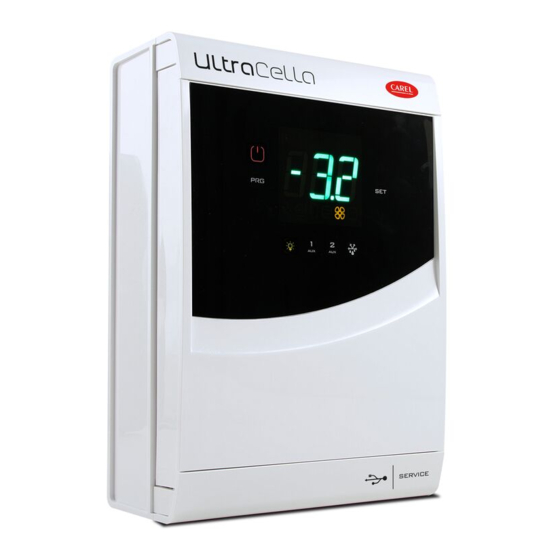
Legenda
1 Campo principale
Main fi eld
2 Assistenza
Service
3 HACCP
HACCP
4 Porta aperta
Door open
5 Compressore
Compressor
6 Ventole evaporatore
Evaporator fans
7 Real Time Clock (RTC)
Real Time Clock (RTC)
8 campo secondario
Second fi eld
HELP
HELP
Tastiera
Tasto Key
Descirzione
Description
• Premuto per 2 s, pone il
• Pressed for 2 sec, switches the
controllo in OFF
controller OFF
• Premuto per 2 s, pone il
• Pressed for 2 sec, switches the
controllo in ON
controller ON
HELP
• Premuto per 2 s, accesso al
• Pressed for 2 sec, accesses the
HELP
menu programmazione
programming menu
• Funzione ESC, ritorno a un
• ESC function, return back up one
HELP
HELP
level
livello superiore
HELP
HELP
• In caso di allarme: tacita
• In the event of alarms: mutes the
HELP
HELP
HELP
l'allarme acustico (buzzer)
audible alarm (buzzer)
• Premuto per 2 s, ripristina gli
• Pressed for 2 sec, resets the
allarmi a ripristino manuale e
alarms with manual reset and
disattiva il relè di allarme
deactivates the alarm relay
Accende/spegne la luce
Light on/off
Accende/spegne l'uscita
Auxiliary output 1 on/off
ausiliaria 1
Accende/spegne l'uscita
Auxiliary output 2 on/off
ausiliaria 2
MENU
MENU
Activates/deactivates the manual
Attiva/disattiva lo sbrinamento
manuale
defrost
• Impostazione set point
• Sets the set point
• Conferma valore
• Confi rms the value
• Incremento / decremento
• Increases / decreases the value
MENU
valore
• When browsing the parameters,
MENU
• Durante la navigazione dei
moves to the next/previous
parametri, passa al parame-
parameter
MENU
MENU
tro successivo/precedente
MENU
MENU
se premuti insieme per
if pressed together for
MENU
MENU
MENU
2 s, accesso al menu multi-
2 sec, accesses the multifunction
funzione
menu
+
HELP
Montaggio con guida DIN
NO POWER
& SIGNAL
CABLES
TOGETHER
READ CAREFULLY IN THE TEXT!
Fissare la guida DIN e inserire il controllo
Power Module –
accessory
Rimuovere le cornici (1 e 2), svitare le viti (3)
e aprire il quadro
Description
Segnare sulla parete le posizioni dei fori
inferiori, rimuovere il quadro ed eseguire i
fori (∅ 4,5 mm); inserire i tasselli
Description
EVD module
Power module with 3
HP relay
1
8
Riagganciare il quadro su guida DIN e fi ssarlo
avvitando le viti inferiori.
4 5 6
Utilizzare le preforature e montare i pressacavi per collegare:
• sul lato inferiore: cavi alimentazione, sonde, attuatori;
• sul lato destro: i cavi per la connessione agli eventuali moduli accessori;.
Attenzione:
• separare i cavi di potenza (alimentazione, attuatori) dai cavi di segnale (sonde,
ingressi digitali)
• utilizzare una sega a tazza per forare il quadro in corrispondenza delle preforature (A).
Keypad
MONTAGGIO E INSTALLAZIONE / ASSEMBLY AND INSTALLATION
DIN rail mounting
Fasten the DIN rail and attach the controller
Remove the faceplates (1 and 2), unscrew the
screws (3) and open the panel
1
2
2
1
Mark the positions of the bottom holes on
the wall, remove the panel and drill the holes
(∅ 4.5 mm); insert the anchors
N
Attach the panel to the DIN rail again and
fasten it by tightening the bottom screws.
A
Dimensioni (mm) / Dimensions (mm)
30
32
200
100
Montaggio senza
guida DIN
Eseguire i 4 fori (∅ 4,5 mm in
base alla dima di foratura) ed
inserire i tasselli
Rimuovere le cornici (1 e 2)
3
3
Avvitare le viti (1) e fi ssare il
quadro
1
1
1
1
Svitare le viti (2) ed aprire il
quadro
Use the knock-outs and fi t the cable glands to connect:
• on the bottom side: power supply, probe, actuator cables;
• on the right side: the cables for connecting any accessory modules.
Warning:
• separate the power cable (power supply, actuators) from the signal cables (probes,
digital inputs)
• use a holesaw to drill the panel in correspondence with the predrilled holes (A).
N
Power Supply, compressor
probes, digital inputs
fan, actuators
Ø 4,5
156
No DIN rail
mounting
Drill the 4 holes (∅ 4.5 mm
based on the drilling template)
and insert the anchors
Remove the faceplates (1 and 2)
1
2
2
1
Tighten the screws (1) and
fasten the panel
1
Unscrew the screws (2) and
open the panel
2
2
Connection
to option
modules
Dima di foratura (mm)/
Drilling template (mm)
156
Advertisement
Table of Contents

Subscribe to Our Youtube Channel
Related Manuals for Carel UltraCella


Summary of Contents for Carel UltraCella
- Page 1 Remove the faceplates (1 and 2) e aprire il quadro screws (3) and open the panel UltraCella è una famiglia di prodotti costi- UltraCella is a family of products com- tuita da un controllo per la gestione delle prising a controller for managing the...
- Page 2 When the temperature measurement is important for temp. di funzionamento: operating temp.: food safety, only the temperature probes suggested by Carel must be used. The manual contains further Max corrente resistiva Relè Carico associato Tipo relè...
Need help?
Do you have a question about the UltraCella and is the answer not in the manual?
Questions and answers