Subscribe to Our Youtube Channel
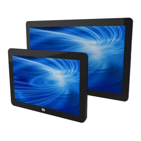
Summary of Contents for Elo TouchSystems ET1002L
- Page 1 USER MANUAL Elo Touch Solutions ET1002L, ET1502L and ET2002L Touchmonitors UM600012 Rev D...
- Page 2 Chapter 2: Installation Unpacking the Touchmonitor Open the carton and verify that the following items are present: • Touchmonitor with Stand (Stand is not included with 1002L monitor) • User Manuals CD • Japanese language regulatory information pamphlet • Quick Install Guide •...
- Page 3 Stand Positions (1502L) The stand of the touchmonitor can be converted between two positions: the low profile “hostess” position and the high profile “upright” position. The touchmonitor ships in the low profile “hostess” position. (1002L monitor does not ship with a stand) Low profile (“hostess”) position To convert the stand into the high profile “upright”...
- Page 4 Connector Panel & Interfaces Touchmonitor Connections 1. Connect the HDMI or Mini-VGA video cables between the m 2. \onitor’s HDMI/Mini-VGA input connectors and your HDMI/VGA video source, respectively. Tighten the video cable’s screws for best performance. 2. Connect the USB touch cable between the monitor’s USB connector and your PC’s USB port.
- Page 5 Installing the Touch Technology Software Drivers No additional drivers are required for your projected-capacitive touchmonitor with Windows 7 and 8 operating systems, it uses Windows HID drivers. If the monitor is used with Windows XP operating system, follow below steps to install Windows XP touch driver. To download latest touch drivers 1.
- Page 6 Chapter 3: Mounting Rear VESA Mount For the 1002L touchmonitor, a four-hole 75x75mm and 100x100mm mounting pattern available.The VESA FDMI-compliant counting is coded: VESA MIS-B, 75, C and VESA MIS- B, 100, C. For the 1502L and 2002L touchmonitors, a four-hole 75x75mm and 100x100mm mounting pattern for M4 screws is provided on the rear of the monitor.
- Page 7 Base Mount For the 1502L touchmonitor, a threaded three-hole mounting pattern for M4 screws is provided on the bottom of stand base for mounting or securing. For the 2002L touchmonitor, threaded through-holes are provided on the bottom of the stand base for mounting or securing. User Manual: 1002L, 1502L, 2002L UM600012 Rev D,...


Need help?
Do you have a question about the ET1002L and is the answer not in the manual?
Questions and answers