
Related Manuals for SPX RADIODETECTION 1205CXB


Summary of Contents for SPX RADIODETECTION 1205CXB
- Page 1 1205CXB ™ Time Domain Reflectometer and Cable Analyser User Guide 90/1205CXB-UG-ENG/02...
- Page 3 Preface Thank you for your interest in Radiodetection’s 1205CXB cable fault locator. ™ Please read this User Guide in its entirety before attempting to use the 1205CXB. Radiodetection products and documents, including this User Guide, are under continuous development. The information contained within is accurate at time of publication;...
- Page 4 Warnings Before using, review all safety precautions. Note and observe all warning and caution statements on the equipment and in the documentation. The 1205CXB contains no user serviceable parts. Do not modify any part or accessory of this instrument. If the unit is damaged, do not use. Also, secure the product from use by others.
-
Page 5: Velocity Of Propagation (Vop)
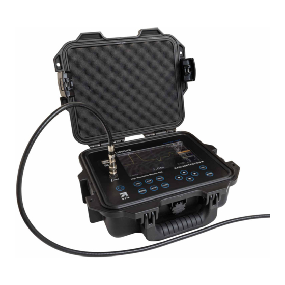
Description The 1205CXB is a Time Domain Reflectometer, also known as a Cable Radar. Electrical pulses are transmitted into a cable, and a portion of the pulse energy is reflected back from cable imperfections. These can be discontinuities (eg cable joints, changes in cable type or the far end of the cable under test) or faults (typically short circuits, open circuits, high resistance joints or water ingress). -
Page 6: User Interface
User interface Features USB port BNC cable connector Display Keypad Name Function Power Turn 1205CXB On and Off ConFiGuration Select parameters and auto search in the ConFiG submenu CURsor Select cursor 1 or 2 WAVEform Select move or zoom function for a waveform MENU Select units, a pre-loaded cable and system settings SAVE... - Page 7 Display features Name Information and use Date Provides date information to stored files Cursor 1 Position for accurate measurement to discontinuities Cursor 2 Position for accurate measurement to discontinuities Launch pulse The pulse sent out by the TDR Reflected pulse(s) Pulse(s) reflected by a cable discontinuity Time measurement Time for the pulse to reach the discontinuity...
-
Page 8: Operation
Operation Press the Power button, 4, to turn 1205CXB on. Connect a cable to the BNC connector, 2. Press the CFG button, 5, repeatedly until VOP is highlighted in the ConFiG submenu, 24. Use the arrow buttons, 11, to set the VOP% to match the VOP% of the cable. -
Page 9: Software Upgrades
For a list of the importers of the 1205CXB into Europe, please visit: https://www.radiodetection.com/en/european-importers Copyright ©2022 Radiodetection Ltd. All rights reserved. Radiodetection is a subsidiary of SPX Corporation. Radiodetection and 1205CXB are either trademarks of Radiodetection in the United States and/or other countries. Due to a policy of continued development, we reserve the right to alter or amend any published specification without notice. - Page 10 Follow us on: Copyright © 2022 Radiodetection Ltd. All rights reserved. Radiodetection is a subsidiary of SPX Corporation. Radiodetection and 1205CXB are either trademarks of Radiodetection in the United States and / or other countries. Due to a policy of continued development, we reserve the right to alter or amend any published specification without notice.
Need help?
Do you have a question about the RADIODETECTION 1205CXB and is the answer not in the manual?
Questions and answers