
Related Manuals for AXIOMTEK DSP511 Series


Summary of Contents for AXIOMTEK DSP511 Series
- Page 1 DSP511 Series Digital Signage Player with 11th Gen Intel® Core™ i5/i3 & Celeron® Processor...
-
Page 2: Disclaimers
Axiomtek does not make any commitment to update any information in this manual. Axiomtek reserves the right to change or revise this document and/or product at any time without notice. No part of this document may be reproduced, stored in a retrieval system, or transmitted in any forms or by any means, electronic, mechanical, photocopying, recording, among others, without prior written permissions of Axiomtek Co., Ltd. -
Page 3: Safety Precautions
Safety Precautions Before getting started, please read the following important safety precautions. The DSP511 does not come with an operating system which must be loaded first before installation of any software into the computer. Be sure to ground yourself to prevent static charge when installing any internal components. -
Page 4: Classifications
Classifications Degree of production against electric shock: not classified Degree of protection against ingress of water: IP40 Equipment not suitable for use in the presence of a flammable anesthetic mixture with air, oxygen or nitrous oxide. Mode of operation: Continuous... -
Page 5: General Cleaning Tips
General Cleaning Tips Please keep the following precautions in mind while understanding the details fully before and during any cleaning of the computer and any components within. A piece of dry cloth is ideal to clean the device. Be cautious of any tiny removable components when using a vacuum cleaner to absorb dirt on the floor. -
Page 6: Scrap Computer Recycling
Scrap Computer Recycling Please inform the nearest Axiomtek distributor as soon as possible for suitable solutions in case computers require maintenance or repair; or for recycling in case computers are out of order. Trademarks Acknowledgments Axiomtek is a trademark of Axiomtek Co., Ltd. -
Page 7: Table Of Contents
Table of Contents Disclaimers ......................ii Safety Precautions ....................iii Classifications ....................... iv General Cleaning Tips ................... v Scrap Computer Recycling ................... vi SECTION 1 INTRODUCTION................. 1 General Descriptions ................. 1 System Specifications ............... 2 1.2.1 CPU ........................2 1.2.2 I/O System ...................... - Page 8 Boot Menu ..................49 Save & Exit Menu ................50 APPENDIX A WATCHDOG TIMER ............. 53 About Watchdog Timer .................. 53 Sample Program ....................54 viii...
-
Page 9: Section 1 Introduction
DSP511 Series user’s Manual SECTION 1 INTRODUCTION This section contains general information and detailed specifica tions of the DSP511. Section 1 consists of the following sub-sections: ◼ General Descriptions ◼ System Specifications ◼ Dimensions ◼ I/O Outlets ◼ Packing List 1.1 General Descriptions... -
Page 10: System Specifications
DSP511 Series user’s Manual Features 11th generation Intel® Core™ i5-1145G7E 4.1GHz, i3-1115G4E 3.9GHz, ⚫ Celeron® 6305E 1.8GHz SoC ⚫ 2 x DDR4-3200 SO-DIMM max. up to 64GB ⚫ 1 COM port, 4 USB ports, 1GbE and 2.5GbE LANs ⚫ 4 HDMI 2.0 for 4K UHD content ⚫... -
Page 11: I/O System
DSP511 Series user’s Manual 1.2.2 I/O System ⚫ Display ◼ 4 x HDMI (HDMI 2.0 up to 4096 x 2160@60Hz) ⚫ Ethernet ◼ 1 x 10/100/1000 Ethernet port (i219LM) ◼ 1 x 10/100/1000/2500 Ethernet port(i225LM) ⚫ USB Ports ◼ 1 x USB 2.0 ◼... -
Page 12: System Specifications
DSP511 Series user’s Manual 1.2.3 System Specifications ⚫ Watchdog Timer ◼ 1~255 seconds or minutes; up to 255 levels. ⚫ Power Supply ◼ 12VDC /84W AC to DC adapter ⚫ Operation Temperature ◼ 0℃ ~+50℃ (32 ºF ~ 122ºF) ⚫... -
Page 13: Dimensions
DSP511 Series user’s Manual 1.3 Dimensions The following diagrams show dimensions and outlines of the DSP511. 1.3.1 System Dimensions Introduction... -
Page 14: Wall/Vesa-Mount Bracket Dimensions
DSP511 Series user’s Manual 1.3.2 Wall/VESA-mount Bracket Dimensions Instruction Step 1: Screw the two pieces of vesa/wall-mount kits to the bottom plate of the device. Total four screws (metric 3 x6) are required. Step 2: Use the device, with wall mount plate attached, as a guide to mark the correct locations of the four screws. -
Page 15: I/O Outlets
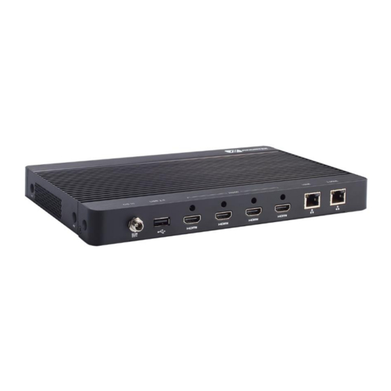
DSP511 Series user’s Manual 1.4 I/O Outlets The following figures show I/O outlets on the DSP511. Front View Rear View 12VDC power input USB 3.2 USB 2.0 RS-232 4x HDMI Clear EDID button GbE LAN Reset button 2.5GbE LAN Power button... -
Page 16: Packing List
DSP511 Series user’s Manual 1.5 Packing List The DSP511 comes with the following bundle package : ⚫ DSP511 System Unit x 1 ⚫ Screw Type AC 84W (12V/7A) Adaptor x 1 ⚫ Optional DDR4 SO-DIMM Memory ⚫ Optional Antenna ⚫... -
Page 17: Section 2 Hardware Installation
DSP511 Series user’s Manual SECTION 2 HARDWARE INSTALLATION The DSP511 is convenient for various hardware configurations such as DRAM, SSD (Solid State Drive) and M.2 modules. Section 2 contains guidelines for hardware installation. 2.1 Installation of SO-DIMM Memory Step 1 Turn off the system and unplug the power cord. - Page 18 DSP511 Series user’s Manual Step 4 Insert a gold-colored contact into the socket and push the module two end latches till locked of the DRAM. Step 5 Put the DRAM cover and fasten one screw back into the system. Hardware Installation...
- Page 19 DSP511 Series user’s Manual 2.2 Installation of SSD Module (M.2 M Key) Step 1 Turn off the system and unplug the power cord. Step 2 Turn the system upside down to locate screws at the bottom then loosen all screws.
- Page 20 DSP511 Series user’s Manual 2.3 Installation of 5G/4G/LTE module (M.2 B Key) Step 1 Turn off the system and unplug the power cord. Step 2 Turn the system upside down to locate screw at the bottom then loosen one screw.
- Page 21 DSP511 Series user’s Manual 2.4 Installation of SIM card module Step 1 Turn off the system and unplug the power cord. Step 2 Turn the system upside down to locate screws at the bottom then loosen all screws. Step 3 Open the TOP cover , located the SIM Card socket on main board.
- Page 22 DSP511 Series user’s Manual 2.5 Installation of M.2 Key E WiFi/BT Module Step 1 Turn off the system and unplug the power cord. Step 2 Turn the system upside down. Locate and loosen the four screws at the bottom, as illustrated below.
-
Page 23: Section 3 Jumper & Connector Settings
3.1 Locations of Jumpers & Connectors SBC87535 Top View Bottom View 【Note】: It is strongly recommended that any unmentioned jumper settings should not be modified without instructions by Axiomtek FAEs. Any modifications without instructions might cause system failure. Jumper & Connector Settings... -
Page 24: Summary Of Jumper Settings
DSP511 Series user’s Manual 3.2 Summary of Jumper Settings Proper jumper settings configure the DSP511 to meet various application purposes. A table of all jumpers and their default settings is listed below. Jumper Description Setting 1-2 Enable (Default) Auto Power On... -
Page 25: Auto Power On (Jp2)
DSP511 Series user’s Manual 3.2.1 Auto Power On (JP2) If the pin 1_2 of JP2 is shorted, the system will be automatically power on without pressing soft power button. If the pin 2_3 of JP2 is shorted, it is necessary to manually press soft power button to power on the system. -
Page 26: Connectors
DSP511 Series user’s Manual 3.3 Connectors Signals go to the other parts of the system through connectors. Loose or improper connection might cause problems. Please make sure all connectors are properly and firmly connected. Here is a table summarizing the connectors on the hardware. -
Page 27: Dc Power Jack Connector (Screw Type) (Cn8)
DSP511 Series user’s Manual 3.3.1 DC Power Jack Connector (screw type) (CN8) The system supports 12V DC-in connector for system power input. The CN8 is a DC jack with a screw. Firmly insert an adapter with at least 84W power output into this connector. To prevent system instability caused by loose connection, make sure all components/devices are properly installed before connecting. -
Page 28: Hdmi Connector (Cn3~Cn6)
DSP511 Series user’s Manual 3.3.3 HDMI Connector (CN3~CN6) The HDMI (High-Definition Multimedia Interface) is a compact digital interface which is capable of transmitting high-definition video and high-resolution audio over a single cable. Pins Signals Pins Signals HDMI OUT_DATA2+ HDMI OUT_DATA2-... -
Page 29: Gbe Lan Port (Cn1)
DSP511 Series user’s Manual 3.3.4 2.5GbE LAN Port (CN1) The system has one RJ-45 connectors: CN1. Ethernet connection can be established by plugging one end of the Ethernet cable into this RJ-45 connector and the other end (phone jack) to a 2500/1000/100/10-Base-T hub. -
Page 30: Atx Power On/Off Button (Cn20)
DSP511 Series user’s Manual Blinking: Data activity detected Speed LED 1000: Orange 100: Green 10: OFF 3.3.6 ATX Power On/Off button (CN20) The ATX power button is on the I/O side. It allows users to control DSP511 power on/off. Functions... -
Page 31: Usb 3.2 Port (Cn15/Cn16/Cn17)
DSP511 Series user’s Manual 3.3.10 USB 3.2 Port (CN15/CN16/CN17) The Universal Serial Bus (compliant with USB 3.2 (5Gb/s)) connector on the rear I/O is for installing USB peripherals such as keyboard, mouse, scanner, etc. Signal Signal CN15/16/17 USB_VCC USB_VCC (+5V_SBY ) -
Page 32: B Key Connector (Cn10)
DSP511 Series user’s Manual 3.3.12 M.2 B Key Connector (CN10) The DSP511 has one M.2 B Key 3052 socket. Pins Signals Pins Signals CONFIG_3 +3.3V +3.3V FULL_CARD_POWER_OFF USB_D+ W_DISABLE1# USB_D- GPIO_9/DAS/DSS#(I/O)/LED1# GPIO_5(I/O) CONFIG_0 GPIO_6(I/O) GPIO_11 GPIO_7(I/O) GPIO_10(I/O) GPIO_8(I/O) PERn1/USB3.0-Rx-/SSIC-RxN UIM-RESET PERp1/USB3.0-Rx+/SSIC-RxP... - Page 33 DSP511 Series user’s Manual ANTCTL0 COEX3 ANTCTL1 COEX2 ANTCTL2 COEX1 ANTCTL3 SIM DETECT RESET# SUSCLK(32kHz) CONFIG_1 +3.3V +3.3V +3.3V CONFIG_2 Jumper & Connector Settings...
-
Page 34: Sim Card Slot (Cn11)
DSP511 Series user’s Manual 3.3.13 SIM Card slot (CN11) This system has one CN11 socket for inserting a SIM Card. In order to work properly, the SIM Card must be used together with a 5G/4G module which is inserted into CN11. It is mainly used in 5G/4G wireless network application. -
Page 35: M Key Connector (Cn13)
DSP511 Series user’s Manual 3.3.14 M.2 M KEY Connector (CN13) This system has one M.2 M key socket for inserting M.2 2280 SATA/NVMe SSD module. Pins Signals Pins Signals +3.3V +3.3V LED1# +3.3V +3.3V +3.3V +3.3V DEVSLP SATA2_RXP SATA2_RXN SATA2_TXN... - Page 36 DSP511 Series user’s Manual Pins Signals Pins Signals +3.3V +3.3V +3.3V Jumper & Connector Settings...
-
Page 37: E Key Connector (Cn12)
DSP511 Series user’s Manual 3.3.15 M.2 E KEY Connector (CN12) The system has one M.2 E Key 2230 socket on the top side supporting PCI Express x1 and USB 2.0. Signal Signal +3.3V USB_D+ +3.3V USB_D- LED1#(I)(OD) PCM_CLK/I2S SCK SDIO CLK(O)(0/1.8V) PCM_SYNC/I2S WS SDIO CMD(IO)(0/1.8V) -
Page 38: Device Management Port (Cn19)
DSP511 Series user’s Manual PEWAKE0#(IO)(0/3.3V) W_DIS1#(I)(0/3.3V) I2C DATA(I0)(0/3.3V) RSVD/PETp1 I2C CLK(I)(0/3.3V) RSVD/PETn1 ALERT#(O)(0/3.3V) RSVD_64 RSVD/PERp1 UIM_SWP/PERST1# RSVD/PERn1 UIM_PWR_SNK/CLKREQ1# UIM_PWR_SRC/GPIO1/PEWAKE1# RSVD/REFCLKP1 +3.3V RSVD/REFCLKN1 +3.3V 3.3.16 Device Management Port (CN19) The system provides one device management port supporting remote device management (RDM) function. Please contact with FAE to get detailed information. -
Page 39: Section 4 Bios Setup Utility
DSP511 Series user’s Manual SECTION 4 BIOS SETUP UTILITY This section provides users with detailed descriptions in terms of how to set up basic system configurations through the BIOS setup utility. 4.1 Starting To enter the setup screens, follow the steps below: Turn on the computer and press the <Del>... -
Page 40: Main Menu
DSP511 Series user’s Manual 4.3 Main Menu The Main Menu screen is the first screen users see when entering the setup utility. Users can always return to the Main setup screen by selecting the Main tab. System Time/Date can be set up as described below. -
Page 41: Advanced Menu
DSP511 Series user’s Manual 4.4 Advanced Menu The Advanced menu also allows users to set configuration of the CPU and other system devices. Users can select any items in the left frame of the screen to go to sub menus: ►... - Page 42 DSP511 Series user’s Manual NCT55250 Super IO Configurations Use this screen to select options for the NCT55250 Super IO Configurations, and change the value of the selected option. A description of the selected item appears on the right side of the screen.
- Page 43 DSP511 Series user’s Manual BIOS Setup Utility...
- Page 44 DSP511 Series user’s Manual Hardware Monitor This screen monitors hardware health status. This screen displays the temperature of the system and CPU as well as system voltages (VBAT and +5V). BIOS Setup Utility...
- Page 45 DSP511 Series user’s Manual Trusted Computing You can use this screen for TPM (Trusted Platform Module)configuration. It also shows current TPM status information. Security Device Support Enable or disable BIOS support for security device. The default is Disabled. Once the Security Device Support is enabled, you will see the following screen.
- Page 46 DSP511 Series user’s Manual CPU Configurations This screen shows the CPU version and its detailed information. Hyper-Threading Enable or disable to the logical processor threads. The default is enabled. Intel (VMX) Virtualization Technology Enable or disable Intel® Virtualization Technology. When enabled, a VMM (Virtual Machine Mode) can utilize the additional hardware capabilities.
- Page 47 DSP511 Series user’s Manual Turbo Mode Enable or disable processor Turbo Mode. The processor can be up to maximum turbo frequency when the system loading becomes higher. BIOS Setup Utility...
- Page 48 DSP511 Series user’s Manual Power Limit 1 This feature configures package power limit 1, in milliwatts. Power Limit 2 This feature configures package power limit 2, in milliwatts. BIOS Setup Utility...
- Page 49 DSP511 Series user’s Manual Storage Configuration This screen specifies NVMe storage information. For items marked with “”, please press <Enter> for more options. BIOS Setup Utility...
- Page 50 DSP511 Series user’s Manual AMT Configuration Enable or disable Active Management Technology BIOS features. The default is Enabled. BIOS Setup Utility...
- Page 51 DSP511 Series user’s Manual USB Configurations This screen specifies USB settings. DSP Configurations The section allows users to flash MCU firmware and EDID emulation. Users can select the items in the left frame of the screen to go to the sub menus:...
- Page 52 DSP511 Series user’s Manual MCU F/W Utility Configuration Use this screen to flash MCU firmware. BIOS Setup Utility...
- Page 53 DSP511 Series user’s Manual EDID auto emulate Use this screen to Enabled or Disable EDID auto emulate function. The default is Disabled. BIOS Setup Utility...
-
Page 54: Chipset Menu
DSP511 Series user’s Manual 4.5 Chipset Menu The Chipset menu allows users to change the advanced chipset settings. Display Timing Adjustment When no display or the monitor can’t be work fine, please try to enable it. It will delay 3 seconds to initialize BIOS. - Page 55 DSP511 Series user’s Manual Wake on LAN Enable Enable or disable the integrated LAN to wake the system. BIOS Setup Utility...
-
Page 56: Security Menu
DSP511 Series user’s Manual 4.6 Security Menu Administrator Password This item indicates whether an administrator password has been set (installed or uninstalled). User Password This item indicates whether a user password has been set (installed or uninstalled). BIOS Setup Utility... -
Page 57: Boot Menu
DSP511 Series user’s Manual 4.7 Boot Menu The Boot menu allows users to change boot options of the system. Setup Prompt Timeout Use this item to set up number of seconds to wait for setup activation key where 65535(0xFFFF) means indefinite waiting. -
Page 58: Save & Exit Menu
DSP511 Series user’s Manual 4.8 Save & Exit Menu The Save & Exit menu allows users to load system configurations with optimal or fail-safe default values. Save Changes and Exit When users have completed the system configuration changes, select this option to leave Setup and return to Main Menu. - Page 59 DSP511 Series user’s Manual Save Changes When completed the system configuration changes, select this option to save changes. Select Save Changes from the Save & Exit menu and press <Enter>. Select Yes to save changes. Discard Changes Select this option to quit Setup without making any permanent changes to the system configurations.
- Page 60 DSP511 Series user’s Manual This page is intentionally left blank. BIOS Setup Utility...
-
Page 61: Appendix Awatchdog Timer
DSP511 Series user’s Manual APPENDIX A WATCHDOG TIMER About Watchdog Timer Software stability is major issue in most applications. Some embedded systems are not watched by human for 24 hours. It is usually too slow to wait for someone to reboot when computer hangs. -
Page 62: Sample Program
DSP511 Series user’s Manual Sample Program #include <pc.h> #include <stdio.h> #define SIO_Index_Port 0x2E #define SIO_Data_Port 0x2F #define SIO_Enter_Configuration_Mode 0x01 #define SIO_Entry_key 0x87 #define SIO_LDN_SEL_REGISTER 0x07 #define SIO_LogicalDevice_WDT 0x08 #define SIO_LogicalDevice_EnableOffset 0x30 #define SIO_LogicalDevice_Enable 0x01 #define SIO_LogicalDevice_Disable 0x00 #define SIO_Offset_Countdown_Type 0xF0... - Page 63 DSP511 Series user’s Manual // Select Logical device : WDT outportw(SIO_Index_Port,SIO_LDN_SEL_REGISTER); outportw(SIO_Data_Port,SIO_LogicalDevice_WDT); // Enable WDT Timer outportw(SIO_Index_Port,SIO_LogicalDevice_EnableOffset); outportw(SIO_Data_Port,SIO_LogicalDevice_Enable); // Select count type for minute type or second type to execute WDT timer // by below method. outportw(SIO_Index_Port,SIO_Offset_Countdown_Type); if(CountdownType == 1) outportw(SIO_Data_Port,SIO_Countdown_Type_Second);...
Need help?
Do you have a question about the DSP511 Series and is the answer not in the manual?
Questions and answers