
Related Manuals for AXIOMTEK DSP500-523 Series


Summary of Contents for AXIOMTEK DSP500-523 Series
- Page 1 DSP500-523 Series Digital Signage Player with 9/8th Gen Intel® Core™ i5/i3 & Celeron® Processor...
-
Page 2: Disclaimers
Axiomtek does not make any commitment to update any information in this manual. Axiomtek reserves the right to change or revise this document and/or product at any time without notice. No part of this document may be reproduced, stored in a retrieval system, or transmitted in any forms or by any means, electronic, mechanical, photocopying, recording, among others, without prior written permissions of Axiomtek Co., Ltd. -
Page 3: Safety Precautions
Safety Precautions Before getting started, please read the following important safety precautions. The DSP501-527 does not come with an operating system which must be loaded first before installation of any software into the computer. Be sure to ground yourself to prevent static charge when installing any internal components. -
Page 4: Classifications
Classifications Degree of production against electric shock: not classified Degree of protection against ingress of water: IP40 Equipment not suitable for use in the presence of a flammable anesthetic mixture with air, oxygen or nitrous oxide. Mode of operation: Continuous... -
Page 5: General Cleaning Tips
General Cleaning Tips Please keep the following precautions in mind while understanding the details fully before and during any cleaning of the computer and any components within. A piece of dry cloth is ideal to clean the device. Be cautious of any tiny removable components when using a vacuum cleaner to absorb dirt on the floor. -
Page 6: Scrap Computer Recycling
Scrap Computer Recycling Please inform the nearest Axiomtek distributor as soon as possible for suitable solutions in case computers require maintenance or repair; or for recycling in case computers are out of order. Trademarks Acknowledgments Axiomtek is a trademark of Axiomtek Co., Ltd. -
Page 7: Table Of Contents
Table of Contents Disclaimers ......................ii Safety Precautions ....................iii Classifications ....................... iv General Cleaning Tips ................... v Scrap Computer Recycling ................... vi SECTION 1 INTRODUCTION................. 1 General Descriptions ................. 1 System Specifications ............... 2 1.2.1 CPU ........................2 1.2.2 I/O System ...................... - Page 8 Security Menu .................. 51 Save & Exit Menu ................53 APPENDIX A WATCHDOG TIMER ............. 55 About Watchdog Timer .................. 55 Sample Program ....................56 viii...
-
Page 9: Section 1 Introduction
DSP500-523 Series user’s Manual SECTION 1 INTRODUCTION This section contains general information and detailed specifications of the DSP500-523. Section 1 consists of the following sub-sections: General Descriptions System Specifications Dimensions I/O Outlets Packing List 1.1 General Descriptions The DSP500-523 is a 4K@60Hz digital signage player that powered by LGA1151 socket ®... -
Page 10: System Specifications
DSP500-523 Series user’s Manual Features generation Intel® Core™ i7/i5/i3 & Celeron® processor LGA1151 socket 8 (CPU TDP max. up to 35W) 2 x DDR4-2400/2666 SO-DIMM max. up to 32GB 1 COM port, 4 USB ports and 1 GbE LANs ... -
Page 11: I/O System
DSP500-523 Series user’s Manual 1.2.2 I/O System Display 3 x HDMI (HDMI 2.0 up to 4096 x 2160@60Hz) Ethernet 1 x 10/100/1000 Ethernet ports (i219LM) USB Ports 4 x USB 3.1 Serial Ports ... -
Page 12: Dimensions
DSP500-523 Series user’s Manual 1.3 Dimensions The following diagrams show dimensions and outlines of the DSP500-523. 1.3.1 System Dimensions Introduction... -
Page 13: Wall-Mount Bracket Dimensions
DSP500-523 Series user’s Manual 1.3.2 Wall-mount Bracket Dimensions Instruction Step 1: Screw the two pieces of wall-mount kits to the bottom plate of the device. Total four screws (metric 3 x6) are required. Step 2: Use the device, with wall mount plate attached, as a guide to mark the correct locations of the four screws. -
Page 14: Vesa-Mount Bracket Dimensions
DSP500-523 Series user’s Manual 1.3.3 VESA-mount Bracket Dimensions Instruction Step 1: Screw the two pieces of wall-mount kits to the bottom plate of the device. Total four screws (metric 3 x6) are required. Step 2: Use the device, with wall mount plate attached, as a guide to mark the correct locations of the four screws. -
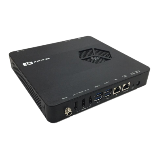
Page 15: I/O Outlets
DSP500-523 Series user’s Manual Tighten the screw head for added stability. 1.4 I/O Outlets The following figures show I/O outlets on the DSP500-523. Front View Rear View 12VDC power input Power Button HDMI 1~3 COM port USB 3.1 Line_Out GbE LAN port... -
Page 16: Packing List
DSP500-523 Series user’s Manual 1.5 Packing List The DSP500-523 comes with the following bundle package : DSP500-523 System Unit x 1 Foot Pad x 4 Screw Type AC 84W (12V/7A) Adaptor x 1 Optional DDR4 SO-DIMM Memory ... -
Page 17: Section 2 Hardware Installation
DSP500-523 Series user’s Manual SECTION 2 HARDWARE INSTALLATION The DSP500-523 is convenient for various hardware configurations such as DRAM, SSD (Solid State Drive) and M.2 modules. Section 2 contains guidelines for hardware installation. 2.1 Installation of the CPU Processor Step 1 Turn off the system and unplug the power cord. - Page 18 DSP500-523 Series user’s Manual Step 5 Installation steps of the CPU Processor Lift the processor package from shipping media by grasping the substrate edges. Scan the processor package gold pads for any presence of foreign material. Locate connection 1 indicator on the processor which aligns with connection 1 indicator chamfer on the socket, and notice processor keying features that line up with posts along socket walls.
- Page 19 DSP500-523 Series user’s Manual Step 6 Installation steps of the CPU processor Align pins of the CPU with pin holes of the socket. Be careful of the CPU’s orientation that users need to align the arrow mark on the CPU with the arrow key on the socket.
-
Page 20: Installation Of So-Dimm Memory
DSP500-523 Series user’s Manual 2.2 Installation of SO-DIMM Memory 1 Installation of DIMM1 Memory Step 1 Turn off the system and unplug the power cord. Step 2 Turn the system upside down to locate screws at the bottom and then loosen four screws. - Page 21 DSP500-523 Series user’s Manual 2 Installation of SDIMM1 Memory Step 1 Turn off the system and unplug the power cord. Step 2 Turn the system upside down to locate screws at the bottom and then loosen four screws. Open the BOTTOM cover.
- Page 22 DSP500-523 Series user’s Manual 2.3 Installation of M.2 SATA/NVMe SSD Step 1 Turn off the system and unplug the power cord. Step 2 Turn the system upside down to locate screws at the bottom and then loosen four screws. Open the BOTTOM cover.
- Page 23 DSP500-523 Series user’s Manual 2.3 Installation of M.2 Key B 4G/LTE Module Step 1 Turn off the system and unplug the power cord. Step 2 Turn the system upside down. Locate and loosen the four screws at the bottom, as illustrated below.
- Page 24 DSP500-523 Series user’s Manual 2.4 Installation of M.2 Key E WiFi/BT Module Step 1 Turn off the system and unplug the power cord. Step 2 Turn the system upside down. Locate and loosen the four screws at the bottom, as illustrated below.
-
Page 25: Section 3 Jumper & Connector Settings
DSP500-523 Series user’s Manual SECTION 3 JUMPER & CONNECTOR SETTINGS Proper jumper settings configure the DSP501-527 to meet various application needs. Hereby all jumpers settings along with their default settings are listed for devices onboard. 3.1 Locations of Jumpers & Connectors... - Page 26 DSP500-523 Series user’s Manual 【Note】: It is strongly recommended that any unmentioned jumper settings should not be modified without instructions by Axiomtek FAEs. Any modifications without instructions might cause system failure. Jumper & Connector Settings...
-
Page 27: Summary Of Jumper Settings
DSP500-523 Series user’s Manual 3.2 Summary of Jumper Settings Proper jumper settings configure the DSP300-318 to meet various application purposes. A table of all jumpers and their default settings is listed below. Jumper Description Setting Auto Power On 1-2 Enable (Default) -
Page 28: Auto Power On (Jp1)
DSP500-523 Series user’s Manual 3.2.1 Auto Power On (JP1) If the pin 1_2 of JP1 is shorted, the system will be automatically power on without pressing soft power button. If the pin 2_3 of JP1 is shorted, it is necessary to manually press soft power button to power on the system. -
Page 29: Connectors
DSP500-523 Series user’s Manual 3.3 Connectors Signals go to the other parts of the system through connectors. Loose or improper connection might cause problems. Please make sure all connectors are properly and firmly connected. Here is a table summarizing the connectors on the hardware. -
Page 30: Dc Power Jack Connector (Screw Type) (Cn7)
DSP500-523 Series user’s Manual 3.3.1 DC Power Jack Connector (screw type) (CN7) The system supports 12V DC-in connector for system power input. The CN16 is a DC jack with a screw. Firmly insert an adapter with at least 60W power output into this connector. To prevent system instability caused by loose connection, make sure all components/devices are properly installed before connecting. -
Page 31: Hdmi Connector (Hdmi1~3)
DSP500-523 Series user’s Manual 3.3.3 HDMI Connector (HDMI1~3) The HDMI (High-Definition Multimedia Interface) is a compact digital interface which is capable of transmitting high-definition video and high-resolution audio over a single cable. Pins Signals Pins Signals HDMI OUT_DATA2+ HDMI OUT_DATA2-... -
Page 32: Atx Power On/Off Button (Sw1)
DSP500-523 Series user’s Manual 3.3.5 ATX Power On/Off button (SW1) The ATX power button is on the I/O side. It allows users to control DSP500-523 power on/off. Functions Descriptions Turn on/off system Keep system status 3.3.6 Clear EDID button (SW2) The clear EDID button allows users to clear the EDID data when the connected display monitors cannot be recognized. -
Page 33: Audio Jack Line-Out Connector (J3)
DSP500-523 Series user’s Manual 3.3.9 Audio Jack Line-out Connector (J3) The DSP500-523 provides one HD audio jack Line_out connector. Pin Color Signal Pink Line-out Jumper & Connector Settings... -
Page 34: B Key Connector (Scn3)
DSP500-523 Series user’s Manual 3.3.10 M.2 B Key Connector (SCN3) The DSP500-523 has one M.2 B Key 3042 socket. Pins Signals Pins Signals CONFIG_3 +3.3V +3.3V FULL_CARD_POWER_OFF USB_D+ W_DISABLE1# USB_D- GPIO_9/DAS/DSS#(I/O)/LED1# GPIO_5(I/O) CONFIG_0 GPIO_6(I/O) GPIO_11 GPIO_7(I/O) GPIO_10(I/O) GPIO_8(I/O) PERn1/USB3.0-Rx-/SSIC-RxN UIM-RESET PERp1/USB3.0-Rx+/SSIC-RxP... -
Page 35: Sim Card Slot (Scn2)
DSP500-523 Series user’s Manual ANTCTL0 COEX3 ANTCTL1 COEX2 ANTCTL2 COEX1 ANTCTL3 SIM DETECT RESET# SUSCLK(32kHz) CONFIG_1 +3.3V +3.3V +3.3V CONFIG_2 3.3.11 SIM Card slot (SCN2) This system has one SCN2 socket for inserting a SIM Card. In order to work properly, the SIM Card must be used together with a 4G/LTE module which is inserted into SCN3. -
Page 36: M Key Connector (Scn1)
DSP500-523 Series user’s Manual 3.3.12 M.2 M KEY Connector (SCN1) This system has one M.2 M key socket for inserting M.2 2280 SATA/NVMe SSD module. Pins Signals Pins Signals +3.3V +3.3V LED1# +3.3V +3.3V +3.3V +3.3V DEVSLP SATA2_RXP SATA2_RXN SATA2_TXN... - Page 37 DSP500-523 Series user’s Manual Pins Signals Pins Signals +3.3V +3.3V +3.3V Jumper & Connector Settings...
-
Page 38: E Key Connector (Scn4)
DSP500-523 Series user’s Manual 3.3.13 M.2 E KEY Connector (SCN4) The system has one M.2 E Key 2230 socket on the top side supporting PCI E xpress x1 and USB 2.0. Signal Signal +3.3V USB_D+ +3.3V USB_D- LED1#(I)(OD) PCM_CLK/I2S SCK SDIO CLK(O)(0/1.8V) -
Page 39: Device Management Port (Lan2)
DSP500-523 Series user’s Manual PEW AKE0#(IO)(0/3.3V) W_DIS1#(I)(0/3.3V) I2C DATA(I0)(0/3.3V) RSVD/PETp1 I2C CLK(I)(0/3.3V) RSVD/PETn1 ALERT#(O)(0/3.3V) RSVD_64 RSVD/PERp1 UIM_SWP/PERST1# UIM_PWR_SNK/CLKREQ RSVD/PERn1 UIM_PWR_SRC/GPIO1/P EWAKE1# RSVD/REFCLKP1 +3.3V RSVD/REFCLKN1 +3.3V 3.3.14 Device Management Port (LAN2) The system provides one device management port supporting remote device management (RDM) function. - Page 40 DSP500-523 Series user’s Manual This page is intentionally left blank. Jumper & Connector Settings...
-
Page 41: Section 4 Bios Setup Utility
DSP500-523 Series user’s Manual SECTION 4 BIOS SETUP UTILITY This section provides users with detailed descriptions in terms of how to set up basic system configurations through the BIOS setup utility. 4.1 Starting To enter the setup screens, follow the steps below: Turn on the computer and press the <Del>... -
Page 42: Main Menu
DSP500-523 Series user’s Manual 4.3 Main Menu The Main Menu screen is the first screen users see when entering the setup utility. Users can always return to the Main setup screen by selecting the Main tab. System Time/Date can be set up as described below. -
Page 43: Advanced Menu
DSP500-523 Series user’s Manual 4.4 Advanced Menu The Advanced menu also allows users to set configuration of the CPU and other system devices. Users can select any items in the left frame of the screen to go to sub menus: ►... - Page 44 DSP500-523 Series user’s Manual F81803 Super IO Configurations Use this screen to select options for the F81803 Super IO Configurations, and change the value of the selected option. A description of the selected item appears on the right side of the screen.
- Page 45 DSP500-523 Series user’s Manual Hardware Monitor This screen monitors hardware health status. This screen displays the temperature of the system and CPU as well as system voltages (VBAT, +3.3V and +5V). BIOS Setup Utility...
- Page 46 DSP500-523 Series user’s Manual ACPI Settings Use this screen to select options for the ACPI configuration, and change the value of the selected option. A description of the selected item appears on the right side of the screen. ACPI Sleep State When the sleep button is pressed, the system will be in the ACPI sleep state.
- Page 47 DSP500-523 Series user’s Manual MCU Configurations Use this screen to Enabled or Disable EDID auto emulate function. The default is Disabled. BIOS Setup Utility...
- Page 48 DSP500-523 Series user’s Manual Trusted Computing You can use this screen for TPM (Trusted Platform Module) configuration. It also shows current TPM status information. Security Device Support Enable or disable BIOS support for security device. The default is Disabled. Once the Security Device Support is enabled, you will see the following screen.
- Page 49 DSP500-523 Series user’s Manual CPU Configurations This screen shows the CPU version and its detailed information. Intel Virtualization Technology Enable or disable Intel Virtualization Technology. When enabled, a VMM (Virtual Machine Mode) can utilize the additional hardware capabilities. It allows a platform to run multiple operating systems and applications independently, hence enabling a single computer system to work as several virtual systems.
- Page 50 DSP500-523 Series user’s Manual SATA And RST Configurations During system boot up, BIOS automatically detects the presence of SATA devices. In the SATA Configuration menu, you can see the currently installed hardware in the SATA ports. SATA Controller(s) Enable or disable the SATA Controller feature. The default is Enabled.
- Page 51 DSP500-523 Series user’s Manual PCH-FW Configuration This screen shows the ME firmware information. BIOS Setup Utility...
- Page 52 DSP500-523 Series user’s Manual AMT Configuration This screen shows the ME firmware information. BIOS Setup Utility...
- Page 53 DSP500-523 Series user’s Manual CSM (Compatibility Support Module) Configuration Use this screen to enable/disable CSM support. Boot optional filter Controls the priority of UEFI and Legacy ROMs. Launch PXE OpROM policy Controls the execution of UEFI and Legacy PXE OpROM.
- Page 54 DSP500-523 Series user’s Manual NVMe Configuration This screen specifies NVMe storage information. For items marked with “”, please press <Enter> for more options. BIOS Setup Utility...
- Page 55 DSP500-523 Series user’s Manual S5 RTC Wake Settings This screen monitors hardware health status. Wake system from S5 Enable or disable system alarm event. The default is Disabled. BIOS Setup Utility...
-
Page 56: Chipset Menu
DSP500-523 Series user’s Manual 4.5 Chipset Menu The Chipset menu allows users to change the advanced chipset settings. Users can select any of the items in the left frame of the screen to go to the sub menus: ► System Agent (SA) Configuration ►... - Page 57 DSP500-523 Series user’s Manual System Agent (SA) Configuration This screen allows users to configure memory parameters. Memory Information Display system memory information. BIOS Setup Utility...
-
Page 58: Pch-Io Configuration
DSP500-523 Series user’s Manual 4.6 PCH-IO Configuration This screen shows the information of South Bridge chipset. For items marked with “”, please press <Enter> for more options. BIOS Setup Utility... -
Page 59: Security Menu
DSP500-523 Series user’s Manual 4.7 Security Menu Administrator Password This item indicates whether an administrator password has been set (installed or uninstalled). BIOS Setup Utility... - Page 60 DSP500-523 Series user’s Manual Boot Menu The Boot menu allows users to change boot options of the system. Setup Prompt Timeout Use this item to set up number of seconds to wait for setup activation key where 65535(0xFFFF) means indefinite waiting.
-
Page 61: Save & Exit Menu
DSP500-523 Series user’s Manual 4.8 Save & Exit Menu The Save & Exit menu allows users to load system configurations with optimal or fail-safe default values. Save Changes and Exit When users have completed the system configuration changes, select this option to leave Setup and return to Main Menu. - Page 62 DSP500-523 Series user’s Manual Save Changes When completed the system configuration changes, select this option to save changes. Select Save Changes from the Save & Exit menu and press <Enter>. Select Yes to save changes. Discard Changes Select this option to quit Setup without making any permanent changes to the system configurations.
-
Page 63: Appendix Awatchdog Timer
DSP500-523 Series user’s Manual APPENDIX A WATCHDOG TIMER About Watchdog Timer Software stability is major issue in most applications. Some embedded systems are not watched by human for 24 hours. It is usually too slow to wait for someone to reboot when computer hangs. -
Page 64: Sample Program
DSP500-523 Series user’s Manual Sample Program The following example enables configurations using debug tool. Enable WDT Enable configuration: O 2E 87; Un-lock super I/O O 2E 87 Select logic device: O 2E 07 O 2F 08 WDT device enable:...
Need help?
Do you have a question about the DSP500-523 Series and is the answer not in the manual?
Questions and answers