Table of Contents
Advertisement
Quick Links
Manual
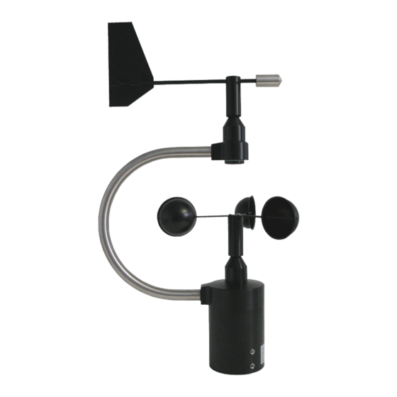
Combined Wind Sensor ARCO-Modbus
ARCO-Modbus · Features and Advantages
▪ Compact and extremely robust wind sensor for measuring
wind direction and wind speed
▪ Friction-free measurement value acquisition through
non-contact measuring principle
▪ Highest reliability by means of precision ball bearings and
high quality measuring elements
▪ Seawater resistant surface finishes for high durability
▪ Low starting value of 0.3 m/s
▪ Very large measuring range from 0.3 to 75 m/s
▪ Quick and easy installation by pipe mounting and M12 plug
connector
(14581) ARCO-Modbus
▪ Integrated, regulated heater for optimal heating of the
sensor heads
▪ Thermal separation between sensor heads and the
housing
▪ Changeable wind vane and three-armed cup anemom-
eter
▪ Sensor head with integrated obstacles prevents infiltra-
tion of water
▪ Digital output (RS485 - Modbus RTU)
▪ The compact design of the sensor reduces the effort with
regard to components and their mounting times upon
comparison with single instruments
Manual
1
Advertisement
Table of Contents

Related Manuals for Lambrecht ARCO-Modbus 14581


![Accessories Lambrecht rain[e]H3 User Manual](https://static-data2.manualslib.com/product-images/f73/2568105/60x60/lambrecht-rain-e-h3.jpg)

Summary of Contents for Lambrecht ARCO-Modbus 14581
- Page 1 Manual Combined Wind Sensor ARCO-Modbus ARCO-Modbus · Features and Advantages ▪ Compact and extremely robust wind sensor for measuring ▪ Integrated, regulated heater for optimal heating of the wind direction and wind speed sensor heads ▪ Friction-free measurement value acquisition through ▪ Thermal separation between sensor heads and the non-contact measuring principle housing ▪ Highest reliability by means of precision ball bearings and ▪ Changeable wind vane and three-armed cup anemom- high quality measuring elements eter ▪ Seawater resistant surface finishes for high durability ▪ Sensor head with integrated obstacles prevents infiltra- tion of water ▪ Low starting value of 0.3 m/s ▪ Digital output (RS485 - Modbus RTU) ▪ Very large measuring range from 0.3 to 75 m/s ▪ The compact design of the sensor reduces the effort with ▪ Quick and easy installation by pipe mounting and M12 plug regard to components and their mounting times upon connector...
-
Page 2: Table Of Contents
Modbus Data Protocols ARCO-Modbus 6.1 General 6.2 Data Encoding 6.3 Standard Configuration - Default 6.4 Available Modbus Commands 6.5 Instantaneous Values / Realtime Values (Input Register) 6.6 Period Data - Average, Maximum and Minimum (Input Register) 6.7 Descriptive Sensor Parameter Registers (Holding Register) 6.8 Configuration Registers (Holding Register) 6.9 Autoconfiguration Technical Data Disposal LAMBRECHT meteo GmbH is listed and registered at the Stiftung Elektro-Altgeräte Register ear under: WEEE-Reg.-No. DE 45445814 In the category of monitoring and control instruments, device type: “Monitoring and control instruments for exclusively com- mercial use”. Within the EU The device has to be disposed according to the European Directives 2002/96/EC and 2003/108/EC (Waste Elec- trical and Electronic Equipment). Do not dispose the old device in the household waste! For an environmentally friendly recycling and disposal of your old device, contact a certified disposal company for electronic waste. Outside the EU Please follow the regulations in your country regarding the appropriate disposal of waste electronic equipment. (14581) ARCO-Modbus Manual... -
Page 3: Introduction
Manual Combined Wind Sensor ARCO-Modbus Introduction The sensor must not be installed on to, or close to, transmitting plants or antennas. A minimum The sensors of the ARCO family are very robust, compact and distance of 2 m is to be kept for interference-free extremely reliable. When developing these sensors particular signal transfer. consideration has been given to the fulfillment of meteorolog- ical requirements. Tools and Installation Aids The system acquires the horizontal air flow and processes the measuring data to the meteorological parameters wind speed There are no special tools or materials required for installation and wind direction. or maintenance. All work can be carried out with standard tools available in a regular workshop. The sensors and further system components are mounted in a splash water resistant and dust-proof metal housing. Unpacking the Sensor The measured data are output via a galvanically isolated RS485 interface via Modbus RTU after switching on the The sensor is packed in a separate box, carefully protected supply voltage. against mechanical influences, in order to avoid damage Due to their shock and vibration proof construction the sensors during transport. When securely installed, the sensor can with- ARCO-Modbus are particularly qualified for use under severe stand shock and vibration, which normally occurs on ships. environmental conditions. The housing and the measuring Please verify that the following parts and documents are elements are made of seawater resistant aluminum alloys. -
Page 4: Mounting The Cup Rotor Of The Wind Speed Sensor
Manual Combined Wind Sensor ARCO-Modbus Mounting the Cup Rotor of the Wind 2.8.1 Alignment of Wind Vane Speed Sensor For wind direction measurements the north mark on the sensor must be aligned with the geographical north direction. The bores at the cup rotor are provided in such a way that the To adjust the wind sensor in a firm and correct manner into cup rotor can only be installed in a certain, clear position. In the north direction this item is equipped with an integrated each case all screws must be used to attach the cup anemom- mounting aid. Inside the inner bottom of the sensor a small bolt eter and wind vane. Thus the correct direction of rotation is pointing to the north is integrated to be set into a correspond- guaranteed. The necessary wrench is included in the delivery. ing slot of the mounting pipe (if available). Thus the sensor is safely attached. If needed you can screw or unscrew the pin by means of an Allen key. You have to turn the marking on the wind vane so that it is exactly over the marking on the sensor shaft. Fix the position of the wind vane with, for example, a piece of adhesive tape. After alignment the adhesive tape has to be removed. When you have fixed the wind vane you can locate the refer- ence point by aiming at it over the axis. Now you must turn the sensor casing on the mounting tube until the tip of the wind vane points to the reference point in the north. -
Page 5: Power And Signal Connection
The external connection is carried out via a central connec- In case you should be faced with any specific problems, which tor which is located in the housing base. For further details you are unable to solve, please contact the LAMBRECHT about the electrical connection please see section "Electrical meteo service: connections“. Tel.: +49-(0)551-4958-0 The typical power supply of the sensors is 24 VDC with a Fax: +49-(0)551-4958-312 current consumption of max. 920 mA (incl. heating). The input voltage range can be 20...28 VDC. The heating of the E-Mail: support@lambrecht.net ARCO-Modbus has a heating power of 2·9 W. Under most climatological conditions the heating prevents Transport blocking of the moving sensor parts. Neither the cup rotor nor the wind vane are heated. In the case of icing or formation In case it is necessary for you to ship or transport the sensor, it of ice on the moving sensor element the function is restricted must be carefully packed to prevent damages during transport. for the period of icing. The output signal of the sensor conforms to the Modbus RTU to RS485 standard. 2.8.3 Safety Regulations Because the wind sensor is often mounted in ex- posed locations at dangerous heights the installation personnel have to pay attention to the relevant safety regulations. During the electrical installation work the external circuitbreaker must be switched off. -
Page 6: Dimensional Drawing And Electrical Connection Arco-Modbus
Manual Combined Wind Sensor ARCO-Modbus Dimensional Drawing and Electrical Connection ARCO-Modbus (14581) ARCO-Modbus Manual... - Page 7 Manual Combined Wind Sensor ARCO-Modbus Electrical connection ARCO-Modbus (14581) ARCO-Modbus Manual...
-
Page 8: Modbus Data Protocols Arco-Modbus
(See www.modbus.org). Data Encoding MODBUS uses the “Big-Endian” format for addresses and data. This means that if a value is transmitted with a number format which is larger than a single byte, that the “most significant byte” is sent first. Example Big-Endian: Register size value 16 - bits 0x1234 is transmitted in the sequence: 0x12 0x34. To obtain the real measuring value, divide the received register value by the divisor. Values of -9999 indicate an internal sensor error. 6.3 Standard Configuration - Default Baud rate: 19200 Baud Byte frame: 8E1 (1 start bit, 8 data bits, 1 parity bit (even parity), 1 stop bit) RTU Sensor address: Default addresses of the LAMBRECHT sensors: Address Sensor Wind speed Wind direction Precipitation rain[e] EOLOS IND · u[sonic]WS6 com[b] PREOS ARCO u[sonic] Pyranometer 2nd Class Secondary standard Pyranometer PT100 to Modbus converter (temperature) u[sonic]WS7 Available Modbus Commands The LAMBRECHT Modbus sensors support the following commands: • “Read Holding Register” command:... -
Page 9: Instantaneous Values / Realtime Values (Input Register)
Manual Combined Wind Sensor ARCO-Modbus Instantaneous Values / Realtime Values (Input Register) The following measured values are provided: Register address Parameter name Unit Divisor Quantity of registers Access type 30001 Wind speed Read only 30201 Wind direction ° Read only 30401 Air temperature °C Read only 30601 Relative humidity % r. F. Read only 30701 Dew point °C Read only... -
Page 10: Descriptive Sensor Parameter Registers (Holding Register)
Manual Combined Wind Sensor ARCO-Modbus Example: Retrieve wind speed (min. max. avr.) and erase the register content LEN Transmission Source Dest Function Func Desk Checksum Query => Master Slave 1 Read Input Register (4) Address=30004, Quantity of Register=1 OK:86A LEN Transmission Source Dest Function Func Desk Data Checksum Response <= Slave 1 Master Read Input Register (4) Byte count=2 00 00 OK:30B9 LEN Transmission Source Dest Function Func Desk Checksum Query =>... -
Page 11: Configuration Registers (Holding Register)
0 = none The device must be restarted after each change of a setting! Example: Change the RTU address from 4 to 1 LEN Transmission Source Dest Function Func Desk Byte count Register values Checksum Query => Master Slave 5 Write Multiple Register (16) Address=40001, Quantity=1 00 01 OK:4806 LEN Transmission Source Dest Function Func Desk Checksum Response <= Slave 5 Master Write Multiple Register (16) Address=40001, Quantity=1 OK:097E 6.9 Autoconfiguration All Lambrecht Modbus sensors offer the experienced user the possibility to implement an auto-configuration in his Modbus master based on additional information stored in the sensor. The necessary information can be found in the document “Lambrecht_Modbus_Autoconfiguration”. (14581) ARCO-Modbus Manual... -
Page 12: Technical Data
± 2 % FS at 0.3...50 m/s of the system shall result in the loss of warranty and Resolution: < 0.1 m/s non-liability. Changes to system components require Starting value: 0.3 m/s express written permission from LAMBRECHT meteo GmbH. These activities must be performed by a qualified Delay distance: technician. The warranty does not cover: *) Remark: In the case of icing and formation of ice at the movable sensor measuring element, the function is restricted for the period of icing. 1. Mechanical damage caused by external impacts (e. g.
Need help?
Do you have a question about the ARCO-Modbus 14581 and is the answer not in the manual?
Questions and answers