Furuno FAR-2218 Installation Manual
Hide thumbs Also See for FAR-2218:

Advertisement

Model
FAR-2318/2328(-NXT)/FAR-2238S(-BB/-NXT/-NXT-BB)/
FAR-2338S(-NXT)/2328W/2338SW/2258/2268DS
SAFETY INSTRUCTIONS ........................i
SYSTEM CONFIGURATION ..................iv
EQUIPMENT LISTS..............................xiv
1. INSTALLATION...............................1-1
1.2 Antenna Unit (S-band Radar) ...........1-10
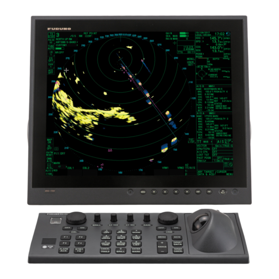
1.3 Monitor Unit.......................................1-18
1.4 Control Unit .......................................1-19
1.5 Power Supply Unit ............................1-25
1.6 Processor Unit ..................................1-27
1.7 Transceiver Unit................................1-28
1.8 Intelligent Hub (option)......................1-29
1.9 Switching Hub (option)......................1-30
1.10 Junction Box (option) ........................1-30
2. WIRING............................................2-1
2.1 Overview .............................................2-1
2.2 Antenna Unit for X-band,
TR-UP Radar......................................2-6
2.3 Antenna Unit for X-band,
TR-DOWN Radar .............................2-19
2.4 Antenna Unit for S-band,
TR-UP Radar....................................2-25
2.5 Antenna Unit for S-band,
TR-DOWN Radar .............................2-37
2.6 Power Supply Unit ............................2-43
2.7 Transceiver Unit................................2-50
2.8 Processor Unit ..................................2-56
2.9 Monitor Unit.......................................2-63
2.10 LAN Signal Converter .......................2-64
2.11 Junction Box (option) ........................2-68
2.12 Intelligent HUB (option).....................2-69
2.13 VDR Connection ...............................2-69
3. ADJUSTMENTS ..............................3-1
All brand and product names are trademarks, registered trademarks or service marks of their respective holders.
Installation Manual
FAR-2218(-BB)/2228(-BB/-NXT/-NXT-BB)/
3.1 How to Open the Radar Installation Menu ..3-3
3.2 How to Align the Heading ...................3-3
3.3 How to Adjust the Sweep Timing ........3-4
3.4 How to Suppress Main Bang ..............3-5
3.5 Other Settings .....................................3-5
3.6 How to Control Charts.......................3-26
4. INPUT/OUTPUT DATA ...................4-1
4.1 Processor Unit ....................................4-1
4.2 Sub Monitor.........................................4-3
APPENDIX 1 JIS CABLE GUIDE.....AP-1
APPENDIX 2 DIGITAL INTERFACE..AP-2
PACKING LISTS ................................. A-1
OUTLINE DRAWINGS ........................ D-1
INTERCONNECTION DIAGRAMS ..... S-1
www.furuno.com
MARINE RADAR

Advertisement

Table of Contents
loading

Summary of Contents for Furuno FAR-2218

  • Page 1: Table Of Contents

    Installation Manual MARINE RADAR FAR-2218(-BB)/2228(-BB/-NXT/-NXT-BB)/ Model FAR-2318/2328(-NXT)/FAR-2238S(-BB/-NXT/-NXT-BB)/ FAR-2338S(-NXT)/2328W/2338SW/2258/2268DS SAFETY INSTRUCTIONS ......i 3.1 How to Open the Radar Installation Menu ..3-3 3.2 How to Align the Heading ....3-3 SYSTEM CONFIGURATION ....iv 3.3 How to Adjust the Sweep Timing ..3-4 EQUIPMENT LISTS......xiv 3.4 How to Suppress Main Bang ....3-5...
  • Page 2 The paper used in this manual is elemental chlorine free. ・FURUNO Authorized Distributor/Dealer 9-52 Ashihara-cho, Nishinomiya, 662-8580, JAPAN : NOV . 2017 Printed in Japan All rights reserved. : MAR. 25, 2021 Pub. No. IME-36520-N21 (AKMU ) FAR-2xx8 series 0 0 0 1 9 8 1 0 4 1 2...
  • Page 3: Safety Instructions

    SAFETY INSTRUCTIONS The installer must read the applicable safety instructions before attempting to operate or install the equipment. Indicates a potentially hazardous situation which, if not avoided, DANGER will result in death or serious injury. WARNING Indicates a potentially hazardous situation which, if not avoided, could result in death or serious injury.
  • Page 4 Model Transceiver Magnetron Antenna* 100 W/m 50 W/m 10 W/m XN12CF 0.6 m 1.4 m 4.4 m Magnetron FAR-2218(-BB) RTR-105 (12 kW) XN20CF 0.4 m 0.9 m 3.0 m FNE1201 radar FAR-2318 XN24CF 0.3 m 0.6 m 2.5 m 1.3 m...
  • Page 5 SAFETY INSTRUCTIONS CAUTION Observe the following compass safe distances to prevent deviation of a magnetic compass: Steering Steering Standard Standard Unit Unit compass compass compass compass Antenna Unit Processor Unit (RPU-025) 1.80 m 2.85 m (X-band, TR-UP, 12 kW, 2.15 m 1.40 m magnetron radar ) 0.80 m...
  • Page 6: System Configuration

    Gyrocompass (or equivalent devices) meeting the requirements of the IMO resolution A.424(XI). • SDME meeting the requirements of IMO resolution MSC.96(72). The radar may be interconnected via HUB-3000 to other FURUNO processing units having approved LAN ports. Standard connection Basic configuration is shown with solid line. For footnotes, see "Notes" on page x.
  • Page 7 SYSTEM CONFIGURATION X-band (TR-UP), 50 kW Antenna Unit for FAR-2258, 50kW : Standard supply (w/ Performance Monitor PM-32A* : Optional or local supply XN24AF-RSB139-122* XN30AF-RSB139-122* Antenna Cable Motor Cable Control Unit RCU-014/ External radar RCU-015/ Power Supply Sub monitor 1 RCU-031* Unit Sub monitor 2...
  • Page 8 SYSTEM CONFIGURATION S-band (TR-UP), 30 kW/250W) Antenna Unit Antenna Unit for FAR-2238S(-BB)/2338S, 30 kW for FAR-2238S-NXT(-BB)/2338S-NXT, 250 W (w/ Performance Monitor PM-52A (w/ Performance Monitor PM-52B SN24CF-RSB129-107* SN24CF-RSB133-111* SN30CF-RSB129-107* SN30CF-RSB133-111* SN36CF-RSB129-107 SN36CF-RSB133-111 Sub monitor Antenna Cable : Standard supply 100-115/220-230 VAC : Optional or local supply 1ø, 50-60 Hz (for de-icer)
  • Page 9 SYSTEM CONFIGURATION S-band (TR-UP), 60 kW Antenna Unit for FAR-2268DS, 60 kW : Standard supply SN30AF-RSB144-129* : Optional or local supply SN36AF-RSB144-129* SN30DF-RSB144-129* Antenna Cable Motor Cable Control Unit RCU-014/ External radar RCU-015/ Power Supply Sub monitor 1 RCU-031* Unit Sub monitor 2 PSU-019 100-115/220-230 VAC...
  • Page 10 SYSTEM CONFIGURATION X-band (TR-DOWN) Antenna Unit for FAR-2328W, 25 kW (w/ Performance Monitor PM-32A) 100-115/220-230 VAC 1ø, 50-60 Hz XN20CF-RSB130 (for de-icer) XN24CF-RSB130 Signal cable Wave guide Transceiver Unit Sub monitor : Standard supply RTR-108 : Optional or local supply Antenna Cable Control Unit RCU-014 or RCU-015...
  • Page 11 SYSTEM CONFIGURATION S-band (TR-DOWN) Antenna Unit for FAR-2338SW, 30 kW (w/ Performance Monitor PM-52A) SN36CF-RSB131 : Standard supply : Optional or local supply 100-115/220-230 VAC 1ø, 50-60 Hz (for de-icer) Signal cable Coaxial cable Transceiver Unit Sub monitor RTR-109 Antenna Cable Control Unit RCU-014 or RCU-015 Gyrocompass*...
  • Page 12 7) Some antenna configurations do not have an in-built Performance Monitor. This type of anten- na is not usable for IMO-type radars. 8) For connecting non-FURUNO ECDIS only. For connection of radars or plotters, the connection must be done at the radar antenna (or the transceiver unit) via the sub monitor connector.
  • Page 13 SYSTEM CONFIGURATION Interswitch connection When multiple radars are used, connect units as shown in the figure below. This configuration lets each radar function as a standalone radar in case of HUB malfunction. Note: This interswitch connection is NOT available between the different softwares (01.xx version and 50.xx version) even the connections between FAR-2xx8 radars.
  • Page 14 SYSTEM CONFIGURATION Radar Component Combinations TRANSCEIVER Band RADAR MODEL ANTENNA UNIT Remarks UP/DN UNIT FAR-2218(-BB), RTR-105 FAR-2318 XN12CF-RSB128 FAR-2228(-BB), RTR-106 XN20CF-RSB128 FAR-2328 XN24CF-RSB128 TR-UP FAR-2228-NXT(-BB), RTR-123 FAR-2328-NXT RTR-122 XN24AF-RSB139 NOT available on FAR-2258 XN30AF-RSB139 IMO-type radars XN20CF-RSB130 TR-DN FAR-2328W RTR-108...
  • Page 15 SYSTEM CONFIGURATION The table below shows those functions which are limited to a specific radar type (Available: , Not available: –). The menus which are not mentioned in the table below are available for all types. This manual provides descriptions for all functions in this radar series. Specification type and function availability in [RADAR INSTALLATION] menu Type Remarks for...
  • Page 16 EQUIPMENT LISTS Standard supply < X-band TR-UP > • Magnetron radar: FAR-2218(-BB)/2228(-BB)/2318/2328 • Solid state radar: FAR-2228-NXT(-BB)/2328-NXT Name Type Code No. Remarks Antenna XN12CF-RSB128-105 4 ft, 12 kW w/ PM-32A* Unit XN12CF-RSB128-106 4 ft, 25 kW (Magnetron XN20CF-RSB128-105 6.5 ft, 12 kW...
  • Page 17 EQUIPMENT LISTS *: Some antenna configurations do not have a built-in Performance Monitor. The Performance Monitor (PM-32A or PM-32B) is mandatory for IMO-type radars. < X-band TR-UP (Fishing specification) > • Magnetron radar: FAR-2258 Name Type Code No. Remarks Antenna Unit XN24AF-RSB139-122 8 ft, 50 kW w/PM-32A*...
  • Page 18: Equipment Lists

    EQUIPMENT LISTS < S-band TR-UP > • Magnetron radar: FAR-2238S(-BB)/2338S • Solid state radar: FAR-2238S-NXT(-BB)/2338S-NXT Name Type Code No. Remarks Antenna Unit SN24CF-RSB129-107 8 ft, • Unavailable on IMO- (Magnetron 30 kW type radars. radar) • w/PM-52A* SN30CF-RSB129-107 10 ft, 30 kW SN36CF-RSB129-107 12 ft,...
  • Page 19 EQUIPMENT LISTS < S-band TR-UP (Fishing specification)> • Magnetron radar: FAR-2268DS Name Type Code No. Remarks Antenna SN30AF-RSB144-129 10 ft, 60 kW Unavailable Unit on IMO-type SN36AF-RSB144-129 12 ft, 60 kW radars. SN30DF-RSB144-129 10 ft, 60 kW, High gain Processor RPU-025 Unit Control Unit...
  • Page 20 EQUIPMENT LISTS < X-band TR-DOWN > • Magnetron radar: FAR-2328W Name Type Code No. Remarks Antenna Unit XN20CF-RSB130 6.5 ft w/PM-32A* XN24CF-RSB130 8 ft Transceiver Unit RTR-108 Processor RPU-025 Unit Monitor Unit MU-231 23.1-inch monitor MU-270W 27-inch monitor Control Unit RCU-014 Standard type RCU-015...
  • Page 21: Installation

    EQUIPMENT LISTS < S-band TR-DOWN > • Magnetron radar: FAR-2338SW Name Type Code No. Remarks Antenna Unit SN36CF-RSB131 12 ft, w/PM-52A* Transceiver Unit RTR-109 Processor RPU-025 Unit Monitor Unit MU-231 23.1-inch monitor MU-270W 27-inch monitor Control Unit RCU-014 Standard type RCU-015 Trackball type Installation...
  • Page 22: Intelligent Hub (Option)

    EQUIPMENT LISTS Console type (RCN-319/323/327/305/306) Name Type Code No. Qty. Remarks Standard RCN-319 For 19-inch monitor Console RCN-323 For 23.1-inch monitor RCN-327 For 27-inch monitor Spare Parts SP03-19200 000-034-305 For X-band radar, S-band (24rpm) radar, without HUBs. SP03-19210 000-034-306 For S-band (42rpm) radar, without HUBs.
  • Page 23: Monitor Unit

    EQUIPMENT LISTS Name Type Code No. Remarks Monitor Unit MU-190 19-inch monitor MU-231 23.1- inch monitor MU-270W 27-inch wide monitor Hood Assembly OP26-6 001-080-930 For MU-190/190HD OP26-16 001-116-740-01 For MU-231 Hood Assembly OP26-32 001-439-090 For MU-270W (Front) Hood Assembly OP26-33 001-439-110 For MU-270W (Rear)
  • Page 24 EQUIPMENT LISTS Name Type Code No. Remarks Cable Assembly XH10P-W-5P-A 001-247-690 For Control Unit (RCU-016), 10 m L=10M XH10P-W-5P-A 001-247-700 For Control Unit (RCU-016), 20 m L=20M XH10P-W-5P-A 001-247-710 For Control Unit (RCU-016), 30 m L=30M XH10P-W-5P-A 001-489-240 For Control Unit (RCU-016), 1.5 m L=1.5M Connection Stand OP03-243...
  • Page 25 EQUIPMENT LISTS Name Type Code No. Remarks Console Replace- OP03-253-1 001-508-160 For FAR-2xx7 console, w/ AD-100 ment Kit OP03-253-2 001-508-170 For FAR-2xx7 console, no AD-100 RP Board OP03-258-1 001-523-270 For software version 01.** Installation Kit OP03-258-4 001-546-980 For software version 50.** Installation CP24-02900(10M) 001-208-050...

Table of Contents