Trane CVHE Installation Instructions Manual
Afdh d-frame retrofit adaptive frequency drive for ucp2, tracer ch531, and tracer adaptiview centrifugal chiller controllers
Hide thumbs
Also See for CVHE:
- Troubleshooting manual (128 pages) ,
- Installation, operation and maintenance manual (100 pages) ,
- Information manual (95 pages)
Table of Contents
Advertisement
Quick Links
Installation Instructions
AFDH D-Frame Retrofit Adaptive
Frequency Drive™
For UCP2, Tracer™ CH531, and Tracer
AdaptiView™ Centrifugal Chiller Controllers
Models
CVHE, CVHF, CVHG
Design Sequence:
D0, E0
Only qualified personnel should install and service the equipment. The installation, starting up, and servicing of
heating, ventilating, and air-conditioning equipment can be hazardous and requires specific knowledge and training.
Improperly installed, adjusted or altered equipment by an unqualified person could result in death or serious injury.
When working on the equipment, observe all precautions in the literature and on the tags, stickers, and labels that are
attached to the equipment.
May 2020
SAFETY WARNING
AFDH-SVN03H-EN
Advertisement
Table of Contents

Related Manuals for Trane CVHE


Summary of Contents for Trane CVHE
- Page 1 AFDH D-Frame Retrofit Adaptive Frequency Drive™ For UCP2, Tracer™ CH531, and Tracer AdaptiView™ Centrifugal Chiller Controllers Models CVHE, CVHF, CVHG Design Sequence: D0, E0 SAFETY WARNING Only qualified personnel should install and service the equipment. The installation, starting up, and servicing of heating, ventilating, and air-conditioning equipment can be hazardous and requires specific knowledge and training.
- Page 2 (Global Harmonized System of Classification and compounds have the same potential impact to the Labeling of Chemicals) guidelines for information on environment. Trane advocates the responsible handling of allowable personal exposure levels, proper all refrigerants-including industry replacements for CFCs respiratory protection and handling instructions.
- Page 3 Follow proper lockout/ servicing of this product. tagout procedures to ensure the power cannot be inadvertently energized. For variable frequency drives or other energy storing components provided by Trane NOTICE or others, refer to the appropriate manufacturer’s Use Copper Conductors Only! literature for allowable waiting periods for discharge of capacitors.
- Page 4 Copyright This document and the information in it are the property of Trane, and may not be used or reproduced in whole or in part without written permission. Trane reserves the right to revise this publication at any time, and to make changes to its content without obligation to notify any person of such revision or change.
-
Page 5: Table Of Contents
Table of Contents Model Number Descriptions Mounted Starter ..... . .23 ....6 Unit Model Number . -
Page 6: Model Number Descriptions
Digit 25— Jumper Size 575 V/600 V No Jumper Bars Required 2B = 192 Maximum RLA 60 Hz Bar Kit 1 For service purposes, Trane Model 0L = 242 Maximum RLA 60 Hz Bar Kit 2 AFDH Air-Cooled drive upgrade 0M =... -
Page 7: General Information
Trane model CVHE and CVHF compressors. AFDH Retrofit Air-Cooled Adaptive Frequency™ Drive Other Literature Required Before (AFD) package in place of an existing starter on a Trane CVHE or CVHF model centrifugal chiller. This only applies Ordering or Installing an AFDH to chillers having either a UCP2™... -
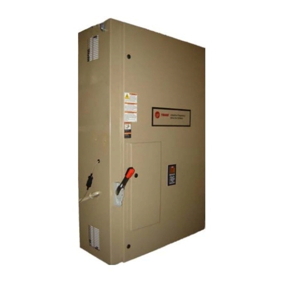
Page 8: Nameplates
Nameplates A nameplate is installed on each AFDH Air-Cooled Drive unit. Always provide the model number and serial number that is printed on this nameplate when making warranty inquiries, ordering parts, or ordering literature for the unit. Figure 1. AFDH nameplate example AFDH-SVN03H-EN... -
Page 9: Pre-Installation
Pre-Installation Confirming the AFDH Package can Figure 2. Example of a direct-mount chiller starter be Properly Installed panel This chapter details potential interference fit problems, mechanical incompatibility situations, electrical code stipulations, and electrical conduit and wiring issues that can prevent the successful installation and/or operation of an AFDH retrofit drive package. -
Page 10: Installation Considerations For Remote Floor-Mounted Afdh
Cooled Adaptive Frequency™ Drive. The potential for damage to occur to the motor windings controller system must first be upgraded to and/or insulation. Trane assumes no responsibility for Tracer® AdaptiView™ before an AFDH retrofit equipment damage caused by use of improper cable package can be installed. -
Page 11: Equipment Room Ambient Temperature Con
These systems are found on conditions are expected to exceed either 104°F for a all Trane® chillers built since 1985. continuous 24-hour period, or where the potential maximum ambient temperatures can exceed 113°F. - Page 12 Pre-Installation Electrical Cable Size Specifications for AFDH Drives AFDH D-Frame drives (460 V/480 V) Table 2. Input/output power wire cable sizes 65K Short Circuit Withstand Rating 281 Catalog/ 336 Catalog/ 413 Catalog/ 500 Catalog/ Catalog/Maximum Amps 301 Maximum 361 Maximum 443 Maximum 535 Maximum Incoming power to drive circuit breaker:...
- Page 13 Pre-Installation AFDH D-Frame drives (380 V/400 V) (continued) Table 3. Input/output power wire cable sizes 100K Short Circuit Withstand Rating 293 Catalog/ 367 Catalog/ 446 Catalog/ 545 Catalog/ Catalog/Maximum Amps 315 Maximum 395 Maximum 480 Maximum 588 Maximum Incoming power to drive circuit breaker: Two Wire Lugs Two Wire Lugs Four Wire Lugs...
-
Page 14: Tools Required
• Loctite® 554 thread sealant for refrigerant already have the majority of the normal tools needed for applications (Trane part number SEL00528). this job. – Used in applications where a pressure In addition to the normally carried service tools and transducer needs to be installed. -
Page 15: Unit Lifting Points
Pre-Installation Unit Lifting Points Alternative Lifting Method • If it is only possible to use a single hoisting device to lift Figure 3. Unit lifting points and center of gravity an AFDH drive unit to position it for installation, a spreader bar should be used to allow adjusting the rigging as necessary to balance the unit around its center-of-gravity to ensure full control of the unit... -
Page 16: Afdh Drive Package Specifications
AFDH Drive Package Specifications D-Frame Drive Unit Mount Dimensions Figure 6. Top, front, and side view of D-Frame AFDH cabinet with dimensions 18.90 15.81" 17.13" UCP2™ or CH531 / Tracer® AdaptiView™ control box Z-bracket mounting studs (each stud = 3/8-16 x 1.75 in.) Two-piece access door cover on top of the 7 in. -
Page 17: Drive Unit Mount Weights And Heat Rejection
AFDH Drive Package Specifications Figure 7. Rear view of D-Frame AFDH cabinet with dimensions Motor terminal access cover. Size of cutout is 8 in. x 16.5 in. Centerline of Z-bracket mounting studs UCP2™ or CH531 / Tracer® AdaptiView™ control box Center-to-center spacing of the mounting notches for the angle iron bracket clips that will be removed from the unit mounted starter being replaced and reused. -
Page 18: D-Frame Drive Remote Mount Dimensions
AFDH Drive Package Specifications D-Frame Drive Remote Mount Dimensions Figure 8. Top, front, and side view of D-Frame drive remote mount with dimensions UCP2™ or CH531 / Tracer® AdaptiView™ control box Access door cover on top of 8.5 x 15.5 incoming power wire cutout Electrical disconnect switch AFDH-SVN03H-EN... - Page 19 AFDH Drive Package Specifications Remote Mount Weights and Heat Rejection Table 8. AFDH D-Frame remote mount unit weights (460 V/480 V) 460 V/V480 V D-Frame AFDH 281 Catalog/ 336 Catalog/ 413 Catalog/ 500 Catalog/ Catalog/Maximum Amps 301 Maximum 361 Maximum 443 Maximum 535 Maximum Unit Weight...
-
Page 20: Drive Unit Component Parts Housed Within The Custom Enclosure
AFDH Drive Package Specifications D-Frame Drive Unit Components Drive Unit Component Parts Housed within the Custom Enclosure Figure 9. Mounting location of D and E-Frame custom Figure 9. (continued) Mounting location of D-Frame enclosure parts custom enclosure parts Right-hand cabinet section houses the TR200 drive module for the unit. -
Page 21: Control Box Components For Ucp2 Version Afdh
AFDH Drive Package Specifications Control Box Components for UCP2 Version AFDH Figure 10. D-Frame AFDH UCP2 control box Figure 11. Buss bar specifications; UCP2 miscellaneous components hardware packages Example of shorting buss bars contained in kit BAR0177 Example of shorting buss bars contained in kit BAR0163 Example of shorting buss bars contained in kit BAR00176 Example of shorting buss bars contained in kit BAR00165 Starter module 2U1... -
Page 22: Control Box Components For Ch531/Tracer Adaptiview Version Afdh
Relay (2K12) 120 Vac Table 11. Part numbers for motor panel transition covers Relay socket for 2K12 Power supply (2A3) Part Description Trane Part # Mnemonic # 10. Terminal blocks; 30 amp 6-inch motor panel transition cover 11. Terminal blocks; 65 amp 506820000100... -
Page 23: Installation
WARNING inadvertently energized. For variable frequency drives or other energy storing components provided by Trane Heavy Objects! or others, refer to the appropriate manufacturer’s Failure to properly lift unit could result in death or literature for allowable waiting periods for discharge of serious injury. -
Page 24: Mechanical Removal Of The Existing Remote-Mounted Starter
These welds can break if not lifted straight up. To ensure a safe lift, Trane recommends 4. Remove the bolts securing the bottom of the starter to drilling a hole and bolting the tabs to the enclosure to the brackets on the evaporator. - Page 25 Installation connecting the panel to the Z-bracket on the motor Figure 14. Removing bottom panel bracket from starter flange. panel brackets 5. While steadying the starter panel to prevent it from tipping forward, carefully begin removing the retaining bolts that connect it to the Z-bracket. Note: The existing Z-bracket and transition cover will be reused and do not need to be removed unless greater access is required to the motor...
-
Page 26: Ment)
Installation Mechanical Installation of a Unit Figure 15. Removing the right tab Mounted D-Frame AFDH (For LiquiFlo Drive Replacement) WARNING Heavy Objects! Failure to follow instructions below or properly lift unit could result in unit dropping and possibly crushing operator/technician which could result in death or serious injury, and equipment or property-only damage. - Page 27 Installation 4. Attach adapter bracket to the bottom of the AFDH panel time. Keep tension on the lift rigging to support the using the 3/8-16 X 1 in. bolt and washer at the bottom weight of the cabinet. right corner (when facing the back of the panel). Figure 18.
- Page 28 Installation Figure 20. Attaching the Z-bracket at the top of the Figure 21. Attaching C-clamp to the adapter bracket panel 11. Use a lubricated 3/8-inch drill bit and drill through the mounting brackets on the evaporator at both of the slots located on the adapter bracket.
-
Page 29: Mechanical Installation Of A Unit Mounted D-Frame Afdh
Installation Figure 22. Drilling through mounting brackets on the Figure 23. Attaching C-clamp to the adapter bracket evaporator Mechanical Installation of a Unit- Mounted D-Frame AFDH WARNING Heavy Objects! Failure to follow instructions below or properly lift unit could result in unit dropping and possibly crushing operator/technician which could result in death or serious injury, and equipment or property-only damage. - Page 30 Installation 4. Slowly lower the cabinet until the clips make contact NOTICE: with the evaporator brackets but do not place the full weight of the cabinet onto the brackets at this time. Improper Unit Lowering! Keep tension on the lift rigging to support the weight of Do not drop the drive cabinet assembly onto the the cabinet.
-
Page 31: Mechanical Installation Of Remote-Mounted D-Frame Afdh And Harmonic Filter
Installation Figure 26. Leveling the AFDH drive cabinet against the NOTICE: Z-bracket Improper Unit Lowering! Do not drop the drive cabinet assembly onto the evaporator mounting brackets when setting it into position! Dropping the cabinet onto the brackets could result in damage to the drive cabinet, the brackets, and/or the evaporator shell. -
Page 32: Electrical Installation (All Afdh Models)
Install Shorting Buss Bars (Unit Mount inadvertently energized. For variable frequency drives or other energy storing components provided by Trane Only) or others, refer to the appropriate manufacturer’s literature for allowable waiting periods for discharge of Note: Shorting buss bars must be installed since the capacitors. -
Page 33: Input Power Wire Installation
Installation Note: In some cases, the top plate with conduit hubs Figure 28. Buss bar installation on compressor motor from the original starter may be reused and terminal board installed over the incoming wire access cut-out on the top of the cabinet, in place of the two- piece access covers. -
Page 34: Grounding Afdh Cabinet
Installation Grounding AFDH Cabinet Output Wiring from the AFDH to the CTV Motor WARNING 1. Remove the cover plate from the motor terminal access cutout on the back of the drive cabinet. Proper Field Wiring and Grounding 2. Feed the six motor leads through the back of the drive Required! cabinet to the compressor motor terminal board. -
Page 35: Harmonic Filter
Installation Harmonic Filter • The area chosen should allow the space required for proper air flow. Adequate clearance for air circulation around the enclosure is a 6 inch (15.25 cm) minimum Unit Description clearance required wherever vents are located in the Optionally, the AFDH may be ordered with a passive cabinet. - Page 36 Installation Notes: WARNING • The field will have to provide the properly sized ground wire based on NEC to bond the filter enclosure. Heavy Objects! • Power connections should be re-torqued after the first Failure to follow instructions below or properly lift unit three to six months of operation and on an annual could result in unit dropping and possibly crushing basis thereafter.
- Page 37 Installation Figure 33. Filter wiring diagram Required Reprogramming of 1. Starter Type: The highest model level of AFD available in the UCP2™ starter type menu parameter is UCP2 Controls the AFDB. The principles of the AFDB control algorithm are the same as the operating principles of AFDH For the chiller to operate properly with the AFDH drive, the model drives.
- Page 38 BPC in the control categories, such as impeller size, contact algorithm. This front panel value is unique because it Trane Global Parts Technical Services. To can be changed externally by the user, or internally by contact them, send a message to the control algorithm.
-
Page 39: Required Reprogramming Of Ch531 Controls
Not Applicable Wye-Delta Non-Comm AFD Impeller Diameter (CPIM) 210–335 Enter CPIM from Unit Nameplate Compressor1: Number of stages CVHE = 3, CVHF = 2 Enter from Unit Nameplate Condenser Pressure Sensor Installed, Not Installed Not Installed Installed TechView Configuration View... -
Page 40: Required Reprogramming Of Tracer Adaptiview Controls
Range Default Setting Recommended Setting Impeller Diameter (CPIM) 210–335 Enter CPIM from Unit Nameplate Number of Stages CVHE = 3, CVHF = 2 Enter from Unit Nameplate Tracer TU Configuration View: Starter Range Default Setting Recommended Setting Stop Delay Time (Contactor Interrupt 1–30 Seconds... - Page 41 Range Default Setting Recommended Setting Enter Chiller Model from Unit Nameplate Unit Type (MODL) CVHE, CVHF, CVHG, CVGF CVHE (Note: only CVHE or CVHF apply) Tracer TU Configuration View: UC800 Range Default Setting Recommended Setting Starter Type Not Applicable Unit Mount Wye-Delta...
-
Page 42: Afdh Startup Procedure
AFDH run functions. demand. Complete all items on the commissioning checklist and 7. Document all information on the Startup log. in the startup procedures for the CVHE and CVHF as defined in the operation maintenance manual or other Drive Settings applicable manual. - Page 43 Table 19 for a list of items that are programmed in Ref./Feedb. value the drive at the factory for use with Trane® chillers. In the Terminal 53 live zero Disable event that the drive needs to be reset, these parameters need to be reprogrammed into the drive.
-
Page 44: Troubleshooting
Follow proper lockout/ tagout procedures to ensure the power cannot be inadvertently energized. For variable frequency drives or other energy storing components provided by Trane or others, refer to the appropriate manufacturer’s literature for allowable waiting periods for discharge of capacitors. -
Page 45: Startup Test Log
Setting Manufacture AFD Control Auto Type Re-Optimization Sensitivity Vender ID Model Number UC800 Starter Type: Unit Mount AFD Trane Setting Tracer TU: Configuration View: Starter Default Volts and Hz Amps Restart Inhibit Stop to Start Time Motor Data: Surge Protection... -
Page 46: Recommended Periodic Maintenance And Inspection
Have a qualified licensed electrician or other individual inadvertently energized. For variable frequency drives who has been properly trained in handling live electrical or other energy storing components provided by Trane components perform these tasks. or others, refer to the appropriate manufacturer’s literature for allowable waiting periods for discharge of 1. -
Page 47: Wiring Diagram Matrix
Wiring Diagram Matrix Table 20. Wiring Diagram Number Description CenTraVac CH531 Wiring Diagram with Danfoss 5071-1335 Adaptive Frequency Drive CenTraVac UCP2 Wiring Diagram with Danfoss 5071-1304 Adaptive Frequency Drive Note: Wiring diagrams are available via e-Library. AFDH-SVN03H-EN... - Page 48 For more information, please visit trane.com or tranetechnologies.com. Trane has a policy of continuous product and product data improvement and reserves the right to change design and specifications without notice. We are committed to using environmentally conscious print practices.
Need help?
Do you have a question about the CVHE and is the answer not in the manual?
Questions and answers