Table of Contents
Advertisement
Quick Links
Advertisement
Table of Contents

Subscribe to Our Youtube Channel
Related Manuals for True blue power TWC15 Series


Summary of Contents for True blue power TWC15 Series
- Page 1 Revision A • February 15, 2022...
- Page 2 This manual provides information intended for use by persons who, in accordance with current regulatory requirements, are qualified to install this equipment. If further information is required, please contact: True Blue Power c/o Mid-Continent Instrument Co., Inc. Attn: Customer Service Dept.
-
Page 3: Table Of Contents
TABLE OF CONTENTS SECTION 1 GENERAL DESCRIPTION 4 INTRODUCTION 4 PHYSICAL ATTRIBUTES 4 TECHNICAL SPECIFICATIONS 6 SECTION 2 PRE-INSTALLATION CONSIDERATIONS 7 COOLING 7 EQUIPMENT LOCATION 7 ROUTING OF CABLES 7 LIMITATIONS 7 MODIFICATIONS 8 ... - Page 4 REVISION HISTORY Date Detail Approved 02/15/2022 Initial release. Manual Number 9019726 • Revision A, February 15, 2022...
-
Page 5: Section 1 General Description
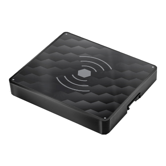
SECTION 1 GENERAL DESCRIPTION INTRODUCTION The TWC15 Series, part numbers 6430015-( ) are Qi Compatible High Power Wireless Chargers. The units are certified accessories that convert 12 to 32 volts of DC electrical input from the aircraft to a maximum of 15 Watts of wireless charging for personal electronic devices (PEDs), such as phones, tablets, etc. - Page 6 Figure 1.2 6430015-2 Drawing Figure 1.3 6430015-3 Drawing Manual Number 9019726 • Revision A, February 15, 2022...
-
Page 7: Technical Specifications
TECHNICAL SPECIFICATIONS TWC15 Models and Type Part Number: Description: 6430015-1 Thin wireless charger – 1 coil 6430015-2 Compact wireless charger – 1 coil 6430015-3 Triple coil wireless charger – 3 coils Table 1.1 Electrical Attributes Input Voltage 12-32 VDC Input Power 26 watts max;... -
Page 8: Section 2 Pre-Installation Considerations
However, compatibility with all devices may not be guaranteed. True Blue Power continues to be proactive in evaluating new devices and strives to continually improve the product as needed to serve the vast majority of Qi Compatible personal electronic devices (PEDs). -
Page 9: Modifications
MODIFICATIONS This product has a nameplate that identifies the manufacturer, part number, description, certification(s) and technical specifications of the unit. It also includes the “MOD” or modification number representing notable changes in the hardware design of the unit. Modification (MOD) 0 is the initial release of the product and is identified on the nameplate by the lack of marking on the MOD numbers 1 through 9 (i.e. -
Page 10: Section 3 Installation
SECTION 3 INSTALLATION GENERAL INFORMATION This section contains interconnect diagrams, mounting dimensions and other information pertaining to the installation of the TWC15 family of Qi Compatible Wireless Chargers. After installation of cabling and before installation of the equipment, ensure that power and ground are applied to the proper pins specified in Section 3.3.2, Pin Assignment Information. - Page 11 3.4.2 Pin Assignment Information and Location See Table 3.2 for pinout definition and Figure 3.1 for pin locations. Pin Number Signal Aircraft Power (12-32 VDC) Ground Status Enable Table 3.2 Wireless Charger Pin Assignment Figure 3.1 Wireless Charger Pin Locations Note: Pins should be crimped using Molex Hand Crimp Tool 213309-1000.
-
Page 12: Installation
3.4.4 Harness Verification Note: The TWS15 High Power Wireless Chargers have built-in reverse polarity protection for the power connector. If Pins 1 and 2 are swapped, the unit will not be damaged, but will also not function. Once the cable harness is prepared, prior to connecting the TWC15, activate the aircraft power bus and use a multimeter to verify that aircraft power and ground are supplied with appropriate voltage on the proper pins within the mating harness. - Page 13 Figure 3.3 Undermount With Threaded Bracket Concept (-1 Configuration Shown) Figure 3.4 Undermount Direct to Charger (-1 Configuration Shown) Figure 3.5 Undermount Direct Mounting to TWC15 Dimensions Manual Number 9019726 • Revision A, February 15, 2022...
- Page 14 Mounting TWC15 units below the panel using a direct mount to the wireless charger requires countersinking holes (see Figure 3.5 above) for a #2 screw. Additionally, the label on top of the wireless charger has 4 small gray dots in each corner. A push pin can be used to punch through the label to allow the 2-56 screws (qty 4) to attach from above per Figure 3.6.
-
Page 15: Section 4 Operation
SECTION 4 OPERATION UNIT ARCHITECTURE The TWC15 Series Wireless Chargers convert an aircraft (DC) input voltage (from 12 to 32 volts) to a wireless charger that can charge personal electronic devices compatible with the Qi wireless specification. The unit is designed as a DC-to-DC converter output regulated to meet the Qi standard that regulates wireless charging up to 15 watts. -
Page 16: Operational Modes And Alarm Conditions
OPERATIONAL MODES AND ALARM CONDITIONS The TWC15 High Power Wireless Chargers provide external status via connector pin #3. Table 4.1 provides indications for all operational modes and alarm conditions. Operational Mode Status Indication Status Indication -1/-2 Units -3 Units Standby Charging 1000ms on, 500ms off 1000ms on, 500ms off... - Page 17 Figure 4.1 Charging Optimal Area (-1) Figure 4.2 Charging Optimal Area (-2) Figure 4.3 Charging Optimal Area (-3) Manual Number 9019726 • Revision A, February 15, 2022...
-
Page 18: Section 5 Conformance
No periodic scheduled maintenance or calibration is necessary for continued airworthiness of the TWC15 series Wireless Chargers. If the unit fails to perform to specifications, the unit must be removed and serviced by Mid-Continent Instruments and Avionics or their authorized designee.
Need help?
Do you have a question about the TWC15 Series and is the answer not in the manual?
Questions and answers