Table of Contents
Advertisement
Quick Links
Advertisement
Table of Contents

Related Manuals for True blue power TA202 Series


Summary of Contents for True blue power TA202 Series
- Page 1 Revision J • June 30, 2020...
- Page 2 This manual provides information intended for use by persons who, in accordance with current regulatory requirements, are qualified to install this equipment. If further information is required, please contact: True Blue Power c/o Mid-Continent Instrument Co., Inc. Attn: Customer Service Dept.
-
Page 3: Table Of Contents
TABLE OF CONTENTS SECTION 1 GENERAL DESCRIPTION 4 1.1 PURPOSE OF EQUIPMENT 4 1.2 TECHNICAL SPECIFICATIONS 5 SECTION 2 PRE-INSTALLATION CONSIDERATIONS 6 2.1 COOLING 6 2.2 EQUIPMENT LOCATION 6 2.3 ROUTING OF CABLES 6 2.4 LIMITATIONS 6 2.5 MODIFICATIONS 7 SECTION 3 ... - Page 4 REVISION HISTORY Date Detail Approved 03/14/2016 Initial release. 04/25/2016 Updated formatting, added AEH statement to table 1.3 Added single port unit mounting options, removed 05/10/2016 configurations table. 06/23/2016 Added two screws (1/4”) to include connector kit. 01/04/2017 Updated to include new mounting option. Added 1.2.4. 05/07/2019 Added single rear mount with cover plate option.
-
Page 5: Section 1 General Description
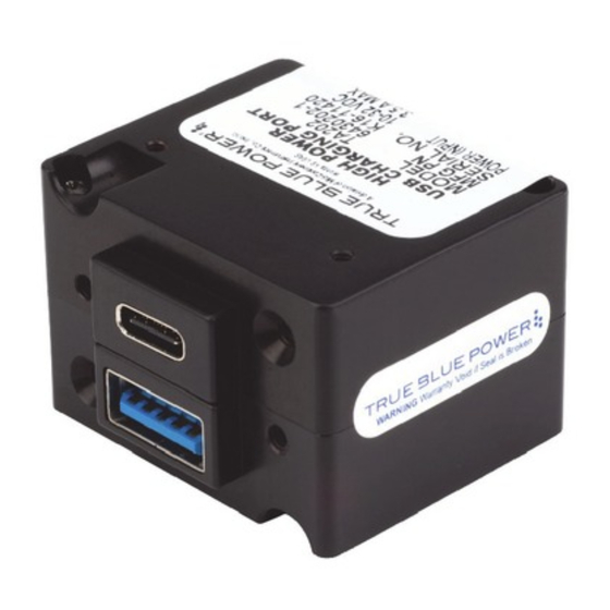
SECTION 1 GENERAL DESCRIPTION PURPOSE OF EQUIPMENT The TA202 Series High Power USB Charging Port is a certified accessory that converts 10 to 32 volts of DC electrical input from the aircraft to standard 5 volt power for any electronic product that charges using a USB connector. -
Page 6: Technical Specifications
TECHNICAL SPECIFICATIONS Electrical Attributes Input Voltage 10-32 VDC Input Power 35 watts max; 2.5 amps @ 14 VDC / 1.25 amps @ 28 VDC Output Voltage 5 VDC ±0.25 per port Output Power 3.0 amps max per port Efficiency ~90% nominal Table 1.1 Physical Attributes Weight... -
Page 7: Section 2 Pre-Installation Considerations
TA202 has been tested with and supports a wide variety of devices now emerging on the open market. However, compatibility with all devices may not be guaranteed. True Blue Power continues to be proactive in evaluating new devices and strives to continually improve the product as needed to serve the vast majority of USB Type-C electronic products. -
Page 8: Modifications
MODIFICATIONS This product has a nameplate that identifies the manufacturer, part number, description, certification(s) and technical specifications of the unit. It also includes the “MOD” or modification number representing notable changes in the hardware design of the unit. Modification (MOD) 0 is the initial release of the product and is identified on the nameplate by the lack of marking on the MOD numbers 1 through 9 (i.e. -
Page 9: Section 3 Installation
SECTION 3 INSTALLATION GENERAL INFORMATION This section contains interconnect diagrams, mounting dimensions and other information pertaining to the installation of the TA202 Single and Dual USB Charger. After installation of cabling and before installation of the equipment, ensure that power and ground are applied to the proper pins specified in Section 3.3.2, Pin Assignment Information. -
Page 10: Mounting
Pin Assignment Information INPUT POWER: Pin A (keyed) – Positive DC input +10 to 32 VDC power Pin B – Negative DC input / ground Note: Pins should be crimped using Molex Hand Crimp Tool 63819-0000 (Preferred), 63811-2800 (obsolete) or 11-01-0200 (obsolete). -
Page 11: Installation Completion
INSTALLATION COMPLETION Prior to operating the unit in the aircraft, it is recommended to verify the output and functionality of the unit. In order to prevent accidental damage to other systems, it is not recommended to attach the output to other equipment prior to verification. Verify the output of the unit at the terminating end of the cable with a multimeter to ensure proper voltage and polarity. - Page 12 Step 1: attach adapter Step 2: attach adapter Figure 3.5 plate to panel Dual Port Instrument Mount Adapter Kit Step 3: loosely attach mounting plate to unit using screws included with unit Step 1: install grommets Step 2: place screw Gap Set Detail through mounting plate (x4) with front...
- Page 13 Latch and front of unit - flush Step 1: install grommets Flush Detail Step 2: place screw through mounting plate (x4) with front latches set flush to front of unit (see detail view) Step 3: place unit in panel Step 4: place adhesive on cutout and secure panel (x2) in locations with screws (x2)
- Page 14 Port protrusion toward top Figure 3.9 Single Port Rear Mount Installation Step 4: place adhesive on panel (x2) in locations Step 3: place unit in panel shown and remove cutout and secure with backing Step 2: Place mounting screws (x2) provided with plate over port unit protrusion...
-
Page 15: Section 4 Operation
SECTION 4 OPERATION ELECTRICAL PERFORMANCE The TA202 Series High Power USB Charging Port converts an aircraft (DC) input voltage within the range specified to a 5V (DC) output. This output power is applied to a single or dual USB-A or USB-C connector in accordance with the USB Implementers Forum. -
Page 16: Section 5 Conformance
No periodic scheduled maintenance or calibration is necessary for continued airworthiness of the TA202 series Single and Dual USB Charger. If the unit fails to perform to specifications, the unit must be removed and serviced by Mid-Continent Instruments and Avionics or their authorized designee.
Need help?
Do you have a question about the TA202 Series and is the answer not in the manual?
Questions and answers