Table of Contents
Advertisement
Installation Manual and Operating Instructions
TA102 Series
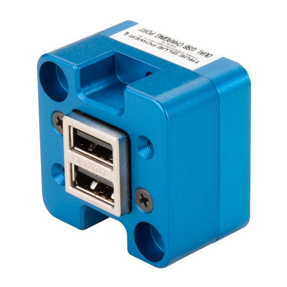
Dual USB Charging Port
True Blue Power® a division of
Mid-Continent Instrument Co., Inc.
Mid-Continent Instrument Co., Inc.
dba Mid-Continent Instruments and Avionics
th
9400 E. 34
Street N.
Wichita, KS 67226
Manual number 9017942
PH (800) 821-1212
FX (316) 630-0723
Rev H, September 12, 2016
Advertisement
Table of Contents

Related Manuals for True blue power TA102


Summary of Contents for True blue power TA102
- Page 1 Installation Manual and Operating Instructions TA102 Series Dual USB Charging Port True Blue Power® a division of Mid-Continent Instrument Co., Inc. Mid-Continent Instrument Co., Inc. dba Mid-Continent Instruments and Avionics 9400 E. 34 Street N. Wichita, KS 67226 Manual number 9017942...
- Page 2 PH (316) 630-0101 FX (316) 630-0723 All products produced by Mid-Continent Instrument, Co., Inc., including those identified as Mid- Continent Instruments and Avionics or True Blue Power, are designed and manufactured in Wichita, KS, USA. ©Copyright 2014 Mid-Continent Instrument, Co., Inc.
- Page 3 Changed information about mounting screws. (PT+0.285” was PT+0.312”) 02/26/15 Added Modification Information, Added Mod 1 09/12/16 Changed the weight in ‘1.2.2 Physical Attributes’ to .13 pounds. ® True Blue Power Manual Number 9017942 Rev H, September 12, 2016 a division of Mid-Continent Instrument Co., Inc.
-
Page 4: Table Of Contents
SHORT CIRCUIT PROTECTION 4.2.2 OVER-CURRENT PROTECTION 4.2.3 LOW INPUT VOLTAGE SHUTDOWN 4.2.4 OVER-TEMPERATURE SECTION 5 CONFORMANCE CONTINUED AIRWORTHINESS STATEMENT ENVIRONMENTAL QUALIFICATION STATEMENT ® True Blue Power Manual Number 9017942 Rev H, September 12, 2016 a division of Mid-Continent Instrument Co., Inc. -
Page 5: Introduction
Apple iPad, other tablets and larger devices can accept and, in some cases, require up to 2.1 amps of power to charge and operate. As a high power DCP, the TA102 can provide up to 2.1 amps of power to charge any USB device, including the higher demand products. -
Page 6: Pre-Installation Considerations
EQUIPMENT LOCATION The TA102 Dual USB Charging Port is designed for mounting flexibility, allowing for installation in the cockpit or in the cabin. It is designed for panel mounting and can be installed in a rectangular or circular rear mount configuration or, with an available installation kit, can be front mounted with a cosmetic cover plate. -
Page 7: Modifications
Modification (MOD) 1 is identified on the nameplate by the marking/blacking out of MOD number 1 (i.e. 1 is not visible and 2-9 are visible see Figure 2.2 below for example). Mod 1 of the TA102 Dual USB Charging Port contains the following changes from MOD 0: Main PC Board Thickness Changed to 0.062” (was 0.031”) -
Page 8: Installation Procedures
This section contains interconnect diagrams, mounting dimensions and other information pertaining to the installation of the TA102 Dual USB Charging Port. After installation of cabling and before installation of the equipment, ensure that power and ground are applied to the proper pins specified in Section 3.3.2, Pin Assignment Information. -
Page 9: Pin Assignment Information
Once the cable harness is prepared, prior to connecting the TA102, activate the aircraft power bus and use a multimeter to verify that aircraft power and ground is supplied with appropriate voltage on the proper pins within the mating harness. -
Page 10: Installation Completion
Panel Cutout Detail Figure 3.3 Rear Mount Installation Panel Cutout Detail Figure 3.4 Circular Rear Mount Installation ® True Blue Power Manual Number 9017942 Rev H, September 12, 2016 a division of Mid-Continent Instrument Co., Inc. - Page 11 Step 5: Peel adhesive backing, align pins on rear of cover plate into holes on mounting plate and press firmly Figure 3.6 Front Mount Installation ® True Blue Power Manual Number 9017942 Rev H, September 12, 2016 a division of Mid-Continent Instrument Co., Inc.
-
Page 12: Electrical Performance
4.2.3 Low Input Voltage Shutdown If the input voltage applied to the TA102 drops below 10 VDC the unit will shut down until the applied voltage returns to a level within range. 4.2.4 Over-Temperature When the temperature of the TA102 becomes elevated, the unit communicates with the USB portable device to reduce the charge current output (1 amp limit). -
Page 13: Continued Airworthiness Statement
SECTION 5 CONFORMANCE CONTINUED AIRWORTHINESS STATEMENT No periodic scheduled maintenance or calibration is necessary for continued airworthiness of the TA102 series Dual USB Charging Port. If the unit fails to perform to specifications, the unit must be removed and serviced by Mid-Continent Instruments and Avionics or their authorized designee.
Need help?
Do you have a question about the TA102 and is the answer not in the manual?
Questions and answers