Table of Contents
Advertisement
Quick Links
Advertisement
Table of Contents

Related Manuals for True blue power TA102 Series


Summary of Contents for True blue power TA102 Series
- Page 1 Revision K • May 14, 2020...
- Page 2 This manual provides information intended for use by persons who, in accordance with current regulatory requirements, are qualified to install this equipment. If further information is required, please contact: True Blue Power c/o Mid-Continent Instrument Co., Inc. Attn: Customer Service Dept.
-
Page 3: Table Of Contents
TABLE OF CONTENTS SECTION 1 GENERAL DESCRIPTION 4 1.1 INTRODUCTION 4 1.2 TECHNICAL SPECIFICATIONS 5 SECTION 2 PRE-INSTALLATION CONSIDERATIONS 6 2.1 COOLING 6 2.2 EQUIPMENT LOCATION 6 2.3 ROUTING OF CABLES 6 2.4 LIMITATIONS 6 2.5 MODIFICATIONS 7 SECTION 3 INSTALLATION PROCEDURES 8 ... - Page 4 REVISION HISTORY Date Detail Approved 04/19/2013 Initial release. 05/30/2013 Updates driven by internal review. Added Circular Rear Mount option and kit details, added 08/22/2013 configurations -2, -3, and -4. Added two additional pins to installation kit and information 11/1/2013 regarding a recommended crimp tool. Added information about adhesive for Front Mount Kit.
-
Page 5: Section 1 General Description
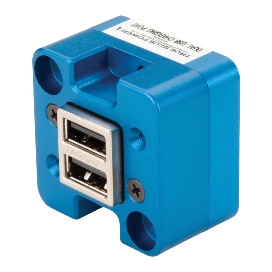
SECTION 1 GENERAL DESCRIPTION INTRODUCTION The TA102 Series Dual USB Charging Port is a certified accessory that converts 10 to 32 volts of DC electrical input from the aircraft to standard 5V power for any electronic product that charges using a USB connector. The TA102 provides two Universal Serial Bus-A (USB-A) ports and can be rear mounted or front mounted in a variety of locations throughout the aircraft. -
Page 6: Technical Specifications
TECHNICAL SPECIFICATIONS Electrical Attributes Input Voltage: 10-32 VDC Input Power: 24 watts max; 1.7 amps @ 14 VDC / 0.85 amps @ 28 VDC Output Voltage: 5 VDC ±0.25 per port Output Power: 2.1 amps max per port Efficiency: ~85% nominal Table 1.1 Physical Attributes Weight:... -
Page 7: Section 2 Pre-Installation Considerations
SECTION 2 PRE-INSTALLATION CONSIDERATIONS COOLING No external cooling is required. The unit will become warm when in use. This is normal and within operational parameters. No special mounting considerations are required; however, mounting to a metal surface can help dissipate any heat generated and extend the life of the product. EQUIPMENT LOCATION The TA102 Dual USB Charging Port is designed for mounting flexibility, allowing for installation in the cockpit or in the cabin. -
Page 8: Modifications
MODIFICATIONS This product has a nameplate that identifies the manufacturer, part number, description, certification(s) and technical specifications of the unit. It also includes the “MOD” or modification number representing notable changes in the hardware design of the unit. Modification (MOD) 0 is the initial release of the product and is identified on the nameplate by the lack of marking on the MOD numbers 1 through 9 (i.e. -
Page 9: Section 3 Installation Procedures
SECTION 3 INSTALLATION PROCEDURES GENERAL INFORMATION This section contains interconnect diagrams, mounting dimensions and other information pertaining to the installation of the TA102 Dual USB Charging Port. After installation of cabling and before installation of the equipment, ensure that power and ground are applied to the proper pins specified in Section 3.3.2, Pin Assignment Information. -
Page 10: Cable Harness
CABLE HARNESS Construct the cable harness following the instructions outlined below and per Figure 3.1. Refer to Section 2: Pre-Installation Considerations, for routing precautions. Wire Gauge Selection Use of PTFE, ETFE, TFE, Teflon or Tefzel insulated wire is recommended for aircraft use. The wire harness should utilize 20-24 AWG stranded wire. -
Page 11: Mounting
MOUNTING The TA102 can be installed in one of four ways: rear mount, rectangular rear mount, circular * instrument mount * front mount, decorative bezel * rear mount, decorative bezel * * installation kit required. See Section 3.2, Optional Equipment Available for part number reference Prepare the panel cutout as shown in Figures 3.3, 3.4, 3.5 or 3.6 per the selected mounting option. -
Page 12: Installation Completion
INSTALLATION COMPLETION Prior to operating the unit in the aircraft, it is recommended to verify the output and functionality of the unit. In order to prevent accidental damage to other systems, it is not recommended to attach the output to other equipment prior to verification. Verify the output of the unit at the terminating end of the cable with a multimeter to ensure proper voltage and polarity. - Page 13 Panel Cutout Detail Figure 3.4 Circular Rear Mount Installation Step 1: attach adapter plate to unit Step 2: attach adapter plate to panel Figure 3.5 Instrument Mount Installation Manual Number 9017942 • Revision K, May 14, 2020...
- Page 14 Step 3: attach mounting plate to unit R.125 1.600±0.025 Step 1: install grommets 1.550±0.010 Step 2: place screw through mounting plate and into pawl latch (x2) Panel Cutout Detail Step 4: place unit through panel cutout. Tighten pawl screws (x2) Figure 3.6 Step 5: Peel adhesive backing, align pins on rear of cover plate into holes on...
-
Page 15: Section 4 Operation
SECTION 4 OPERATION ELECTRICAL PERFORMANCE The TA102 Series Dual USB Charging Port converts an aircraft (DC) input voltage within the range specified to a 5V (DC) output. This output power is applied to a dual USB-A connector in accordance with the USB Implementers Forum. -
Page 16: Section 5 Conformance
No periodic scheduled maintenance or calibration is necessary for continued airworthiness of the TA102 series Dual USB Charging Port. If the unit fails to perform to specifications, the unit must be removed and serviced by Mid-Continent Instruments and Avionics or their authorized designee.
Need help?
Do you have a question about the TA102 Series and is the answer not in the manual?
Questions and answers