Table of Contents
Advertisement
Quick Links
Advertisement
Table of Contents

Summary of Contents for Quantum VSI
- Page 1 Basic Operation Instructions Controller ™...
- Page 2 Safety Guidelines WARNING! A Pride/Quantum Provider or a qualified technician must perform the initial setup of this product and must perform all of the instructions in this manual. The symbols below are used throughout this owner's manual and on the product to identify warnings and important information.
-
Page 3: Table Of Contents
Table of Contents Label Information ..........................4 Introduction ............................5 VSI Controller ............................6 Precautionary Guidelines ........................6 Operating the VSI Controller ......................9 Locking/Unlocking the VSI ....................... 14 Actuator Adjustment ........................14 Sleep Mode ............................14 Thermal Rollback ..........................15 Fault Codes ............................ -
Page 4: Label Information
EMI/RFI—This product has been tested and passed at an immunity level of 20 V/m. Disposal and recycling—Contact your Quantum Rehab Provider for information on proper disposal and recycling of your Quantum product and its packaging. -
Page 5: Introduction
Pride/Quantum to enhance or preserve the safe use of this product. -
Page 6: Vsi Controller
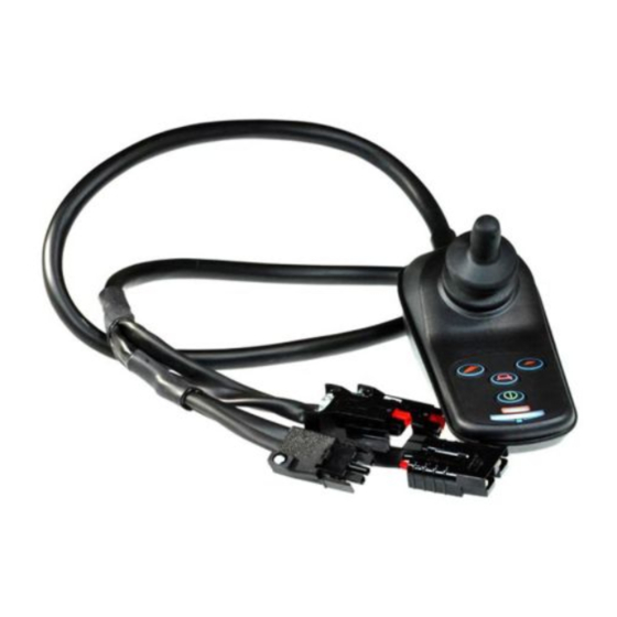
Precautionary Guidelines Before operating the VSI Controller, please read the following. These guidelines are provided for your benefit and will aid you in the safe operation of the controller system. Turn off the power to the controller when transferring to or from your power chair. - Page 7 Contact your Pride/Quantum Provider to report the incident. VSI Controller Features Figure 1 provides information on the VSI components and connections. Use this diagram to familiarize yourself with the function and location of each component before using the VSI Controller.
- Page 8 Programming Socket Connects to battery charger plug or programmer. Ferrite Core Reduces electromagnetic emissions. 9-Pin Beau Connector Harness Main power cable which accepts battery voltage and sends motor signals to the power chair. Figure 1. VSI Components and Connections (9-Pin Configuration)
-
Page 9: Operating The Vsi Controller
Operating the VSI Controller The VSI Controller is used to operate your power chair and all of its components. See figures 2, 3, and 4. The VSI controller may consist of: 1. joystick 2. keypad 3. 3-pin off-board charger/programming socket 4. - Page 10 WARNING! Always turn the power off when you are stationary to prevent unexpected movement. BATTERY CONDITION METER MAXIMUM SPEED/PROFILE INDICATOR ON/OFF KEY SPEED/PROFILE SPEED/PROFILE DECREASE KEY INCREASE KEY HORN KEY Figure 5. VSI Keypad (4-Key)
- Page 11 LIGHT *ACTUATOR *ACTUATOR SPEED/PROFILE SPEED/PROFILE INCREASE KEY DECREASE KEY HORN KEY *FOR OPTIONAL EQUIPMENT ON SOME MODELS Figure 6. VSI Keypad (6-Key) BATTERY CONDITION METER MAXIMUM SPEED/PROFILE ON/OFF KEY INDICATOR LIGHT KEY HAZARD LIGHTS RIGHT TURN SIGNAL LEFT TURN SIGNAL...
- Page 12 Battery Condition Meter The battery condition meter is located in front of the joystick. This is a 10-segment illuminated display that indicates that the VSI is powered on and also gives the battery status, the VSI status, and the electrical system status.
- Page 13 6-Pin Actuator Connector (For Optional Equipment) This connects the VSI to optional equipment such as a lighting system or a power elevating seat. It is typically mounted on the power base. Refer to your power chair owner’s manual for exact location.
-
Page 14: Locking/Unlocking The Vsi
The VSI has a feature that enables you to lock your power chair to prevent unauthorized use. To lock the VSI: 1. With the VSI powered on, press and hold the on/off key. After one (1) second, the VSI should beep. 2. Release the on/off key. -
Page 15: Thermal Rollback
100 times per second. If the VSI detects a problem either in its own circuits or in the power chair’s electrical system, it may decide to stop the power chair, depending on the severity of the problem. The VSI is designed to maximize the user’s safety under all normal conditions. -
Page 16: Care And Maintenance
Care and Maintenance Refer to your power chair owner’s manual for proper cleaning and disposal instructions. Warranty Refer to your power chair owner’s manual for specific information on the controller warranty. - Page 20 401 York Avenue Duryea, PA 18642 Canada 5096 South Service Road Beamsville, Ontario L0R 1B3 32 Wedgwood Road Bicester, Oxfordshire OX26 4UL www.quantumrehab.co.uk Australia 20-24 Apollo Drive Hallam, Victoria 3803 www.quantumrehab.com.au New Zealand 38 Lansford Crescent Avondale Auckland, New Zealand 1007 www.pridemobility.co.nz Italy Via del Progresso, ang.


Need help?
Do you have a question about the VSI and is the answer not in the manual?
Questions and answers