Table of Contents
Advertisement
Quick Links
Advertisement
Table of Contents

Related Manuals for Gigabyte GA-Z270-Gaming K3


Summary of Contents for Gigabyte GA-Z270-Gaming K3
- Page 1 GA-Z270-Gaming K3 User's Manual Rev. 1001 12ME-Z27GMK3-1001R For more product details, please visit GIGABYTE's website. To reduce the impacts on global warming, the packaging materials of this product are recyclable and reusable. GIGABYTE works with you to protect the environment.
- Page 2 The trademarks mentioned in this manual are legally registered to their respective owners. Disclaimer Information in this manual is protected by copyright laws and is the property of GIGABYTE. No part of this manual may be reproduced, copied, translated, transmitted, or published in any form or by any means without GIGABYTE's prior written permission.
-
Page 3: Table Of Contents
Table of Contents GA-Z270-Gaming K3 Motherboard Layout ..............4 Chapter 1 Hardware Installation ..................5 Installation Precautions ..................5 ..................6 Installing the CPU .................... 9 Installing the Memory ..................9 Installing an Expansion Card ................. 10 Back Panel Connectors .................. 10 Internal Connectors .................. -
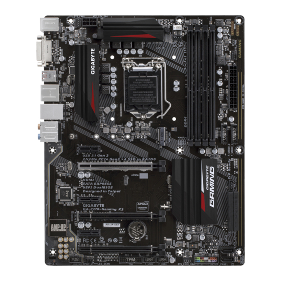
Page 4: Ga-Z270-Gaming K3 Motherboard Layout
GA-Z270-Gaming K3 Motherboard Layout ATX_12V_2X4 KB_MS_USB30 CPU_FAN SYS_FAN1 CPU_OPT SYS_FAN2 LGA1151 ASMedia ® USB 3.1 Gen 2 Controller USB_LAN GA-Z270-Gaming K3 PCIEX1_1 PCIEX16 Killer ™ E2500 LAN THB_C Intel Z270 ® PCIEX1_2 ® Super I/O PCIEX4_1 PCIEX1_3 M_BIOS PCIEX4_2 B_BIOS... -
Page 5: Chapter 1 Hardware Installation
Chapter 1 Hardware Installation Installation Precautions The motherboard contains numerous delicate electronic circuits and components which can become manual and follow these procedures: Prior to installation, make sure the chassis is suitable for the motherboard. warranty sticker provided by your dealer. These stickers are required for warranty validation. Always remove the AC power by unplugging the power cord from the power outlet before installing or removing the motherboard or other hardware components. - Page 6 Z270 Express Chipset Memory memory is installed, the actual memory size displayed will be less than the size of the physical memory installed. (Go to GIGABYTE's website for the latest supported memory speeds and memory Onboard Integrated Graphics Processor-Intel ®...
- Page 7 Chipset+ASMedia ® USB 3.1 Gen 2 Controller: 1 x USB Type-C ™ port on the back panel, with USB 3.1 Gen 2 support Chipset: 8 x USB 3.1 Gen 1 ports (4 ports on the back panel, 4 ports available through 6 x USB 2.0/1.1 ports (2 ports on the back panel, 4 ports available through Internal 1 x 24-pin ATX main power connector...
- Page 8 Windows 7. Form Factor ATX Form Factor; 30.5cm x 24.4cm prior notice. Please visit GIGABYTE's website Please visit the Support\Utility List for support lists of CPU, memory page on GIGABYTE's website to download the latest version of apps. - 8 -...
-
Page 9: Installing The Cpu
Memory modules have a foolproof design. A memory module can be installed in only one direction. If you are unable to insert the memory, switch the direction. Channel memory mode will double the original memory bandwidth. Please visit GIGABYTE's website for details on hardware installation. - 9 -... -
Page 10: Installing An Expansion Card
The four memory sockets are divided into two channels and each channel has two memory sockets as following: 2 Modules 4 Modules of the same capacity, brand, speed, and chips be used and installed in the same colored sockets. Installing an Expansion Card Make sure the motherboard supports the expansion card. - Page 11 The line out jack. Use this audio jack for a headphone or 2-channel speaker. This jack can be used to Mic In (Pink) The Mic in jack. Please visit GIGABYTE's website for more software information. When removing the cable connected to a back panel connector, rst remove the cable from your device and then remove it from the motherboard.
-
Page 12: Internal Connectors
Internal Connectors ATX_12V_2X4 F_AUDIO SPDIF_O CPU_FAN F_USB30_1/F_USB30_2 SYS_FAN1/2 F_USB1/F_USB2 CPU_OPT SYS_FAN3_PUMP THB_C SATA EXPRESS SATA3 0/1/2/3/4/5 CLR_CMOS M2M_32G CPU/DRAM/VGA/BOOT F_PANEL First make sure your devices are compliant with the connectors you wish to connect. Before installing the devices, be sure to turn off the devices and your computer. Unplug the power cord from the power outlet to prevent damage to the devices. - Page 13 1/2) ATX_12V_2X4/ATX (2x4 12V Power Connector and 2x12 Main Power Connector) With the use of the power connector, the power supply can supply enough stable power to all the components off and all devices are properly installed. The power connector possesses a foolproof design. Connect the power supply cable to the power connector in the correct orientation.
- Page 14 5) CPU_OPT (Water Cooling CPU Fan Header) The fan header is 4-pin and possesses a foolproof insertion design. Most fan headers possess a foolproof insertion design. When connecting a fan cable, be sure to connect it in the correct orientation (the black control design.
- Page 15 9) M2M_32G (M.2 Socket 3 Connector) the Intel ® Chipset. Step 1: Use a screw driver to unfasten the screw and nut from the motherboard. Locate the proper mounting hole Step 2: Step 3: Installation Notices for the M.2, and SATA Connectors: affected by the type of device installed in the M2M_32G connector.
- Page 16 10) F_PANEL (Front Panel Header) Connect the power switch, reset switch, speaker, chassis intrusion switch/sensor and system status indicator on the chassis to this header according to the pin assignments below. Note the positive and negative pins before connecting the cables. PLED/PWR_LED Power Switch Speaker...
- Page 17 12) SPDIF_O (S/PDIF Out Header) This header supports digital S/P IF Out and connects a S/P IF digital audio cable (provided by expansion cards for digital audio output from your motherboard to certain expansion cards like graphics cards and sound cards. For example, some graphics cards may require you to use a S/P IF digital audio cable for digital audio output from your motherboard to your graphics card if you wish to connect an H MI display to the graphics card and have digital audio output from the H MI display at the same time.
- Page 18 LCLK No Pin SB3V VCC3 16) THB_C (Thunderbolt Add-in Card Connector) ™ This connector is for a GIGABYTE Thunderbolt ™ add-in card. Supports a Thunderbolt ™ add-in card. 17) BAT (Battery) level, or the CMOS values may not be accurate or may be lost.
- Page 19 18) CLR_CMOS (Clear CMOS Jumper) the CMOS values, use a metal object like a screwdriver to touch the two pins for a few seconds. Open: Normal Short: Clear CMOS Values Always turn off your computer and unplug the power cord from the power outlet before clearing the CMOS values.
-
Page 20: Chapter 2 Bios Setup
Chapter 2 BIOS Setup saving system parameters and loading operating system, etc. BIOS includes a BIOS Setup program that allows When the power is turned off, the battery on the motherboard supplies the necessary power to the CMOS to Q-Flash allows the user to quickly and easily upgrade or back up BIOS without entering the operating system. and updates the BIOS. - Page 21 M.I.T. Whether the system will work stably with the overclock/overvoltage settings you made is dependent on your overall and reduce the useful life of these components. This page is for advanced users only and we recommend you not to alter the default settings to prevent system instability or other unexpected results. (Inadequately altering the settings Advanced Frequency Settings CPU Base Clock Important: It is highly recommended that the CPU frequency be set in accordance with the CPU...
- Page 22 Advanced CPU Core Settings CPU Clock Ratio, CPU Frequency, FCLK Frequency for Early Power On The settings above are synchronous to those under the same items on the Advanced Frequency Settings menu. AVX Offset (Note) AVX offset is the negative offset of AVX ratio. Uncore Ratio Allows you to set the CPU Uncore ratio.
- Page 23 C3 State Support (Note 1) Allows you to determine whether to let the CPU enter C3 mode in system halt state. When enabled, the CPU core frequency and voltage will be reduced during system halt state to decrease power consumption. The C3 state is a more enhanced power-saving state than C1.
- Page 24 System Memory Multiplier Allows you to set the system memory multiplier. Auto Memory Ref Clock Memory Odd Ratio(100/133 or 200/266) Memory Frequency (MHz) is the memory frequency that is automatically adjusted according to the System Memory Multiplier settings. Advanced Memory Settings (Note ) , System Memory Multiplier, Memory Ref Clock, Memory Odd Ratio(100/133 or 200/266), Memory Frequency(Mhz)
- Page 25 Channel A/B Memory Sub Timings This sub-menu provides memory timing settings for each channel of memory. The respective timing setting Memory Timing Mode is set to Manual or Advanced Manual. Note: Your system may become unstable or fail to boot after you make changes on the memory timings. If this occurs, please reset the board to default values by loading optimized defaults or clearing the CMOS values.
- Page 26 Smart Fan 5 Settings Monitor Fan Speed Control Allows you to determine whether to enable the fan speed control function and adjust the fan speed. Normal Allows the fan to run at different speeds according to the temperature. You can adjust the fan speed with System Information Viewer based on your system requirements.
-
Page 27: System
System This section provides information on your motherboard model and BIOS version. You can also select the default language used by the BIOS and manually set the system time. Access Level set, the default will display as Administrator BIOS settings; the User level only allows you to make changes to certain BIOS settings but not all. System Language Selects the default language used by the BIOS. -
Page 28: Bios
A password is required for booting the system and for entering the BIOS Setup program. Full Screen LOGO Show Allows you to determine whether to display the GIGABYTE Logo at system startup. Disabled skips the Boot Option Priorities Or if you want to install an operating system that supports GPT partitioning such as Windows 7 64-bit, select Hard Drive/CD/DVD ROM Drive/Floppy Drive/Network Device BBS Priorities presents the devices of the same type that are connected. - Page 29 SATA Support boot process completes. Fast Boot is set to Enabled or Ultra Fast. VGA Support Allows you to select which type of operating system to boot. Fast Boot is set to Enabled or Ultra Fast. USB Support Full Initial All USB devices are functional in the operating system and during the POST.
- Page 30 Storage Boot Option Control CSM Support is set to Enabled. Other PCI devices than the LAN, storage device, and graphics controllers. CSM Support is set to Enabled. Administrator Password all BIOS settings. User Password Setup. However, the user password only allows you to make changes to certain BIOS settings but not all. - 30 -...
-
Page 31: Peripherals
Peripherals Initial Display Output graphics. OnBoard LAN Controller If you wish to install a 3rd party add-in network card instead of using the onboard LAN, set this item to EZ RAID Ambient LED Intel Platform Trust Technology (PTT) Enables or disables Intel ®... - Page 32 Trusted Computing Intel(R) Bios Guard Technology Enables or disables the Intel ® BIOS Guard feature, which protects the BIOS from malicious attacks. Network Stack Ipv4 PXE Support Network Stack is enabled. Ipv4 HTTP Support Network Stack is enabled. Ipv6 PXE Support Network Stack is enabled.
- Page 33 Mass Storage Devices is installed. SATA Controller(s) SATA Mode Selection to AHCI mode. Aggressive LPM Support Port 0/1/2/3/4/5 Hot plug Enables or disables support for external SATA devices. - 33 -...
-
Page 34: Chipset
Chipset VT-d (Note) Enables or disables Intel ® Internal Graphics DVMT Pre-Allocated DVMT Total Gfx Mem Audio Controller If you wish to install a 3rd party add-in audio card instead of using the onboard audio, set this item to Disabled. High Precision Timer IOAPIC 24-119 Entries Intel... -
Page 35: Power
Power Platform Power Management PEG ASPM Platform Power Management is set to Enabled PCH ASPM Platform Power Management is set to Enabled DMI ASPM Platform Power Management is set to Enabled AC BACK Always On The system is turned on upon the return of the AC power. Memory The system returns to its last known awake state upon the return of the AC power. - Page 36 Power On By Mouse Allows the system to be turned on by a PS/2 mouse wake-up event. Note: To use this function, you need an ATX power supply providing at least 1A on the +5VSB lead. Move Move the mouse to turn on the system. Note: When this item is set to Enabled PME event wake up, power on by mouse, power on by keyboard, and wake on LAN.
-
Page 37: Save & Exit
Save & Exit Save & Exit Setup Yes. This saves the changes to the CMOS and exits the BIOS Setup program. Select No Exit Without Saving Yes. This exits the BIOS Setup without saving the changes made in BIOS Setup to the CMOS. Select No Load Optimized Defaults Yes to load the optimal BIOS default settings. -
Page 38: Chapter 3 Appendix
Chapter 3 Appendix RAID Levels RAID 0 RAID 1 RAID 5 RAID 10 Minimum Number of Hard Array Capacity Number of hard Size of the smallest (Number of hard (Number of hard drives * Size of the drive smallest drive the smallest drive smallest drive Fault Tolerance... - Page 39 Steps: 1. In BIOS Setup, go to BIOS and set Windows 8/10 Features to Windows 8/10 and CSM Support to Disabled. Save the changes and exit BIOS Setup. 2. After the system reboot, enter BIOS Setup again. Then enter the Peripherals\Intel(R) Rapid Storage Technology sub-menu.
- Page 40 After installing the operating system, insert the motherboard driver disk into your optical drive. Click install. You can click the Xpress Install the arrow icon to individually install the drivers you need. Please visit GIGABYTE's website Please visit GIGABYTE's website for more software information. for details on configuring the audio software.
- Page 41 Contravention will be prosecuted. We believe that the information contained herein was accurate in all respects at the time of printing. GIGABYTE cannot, however, assume any responsibility for errors or omissions in this text. Also note that the information in this document is subject to change without notice and should not be construed as a commitment by GIGABYTE.
- Page 42 FCC Notice (U.S.A. Only) This equipment has been tested and found to comply with the limits for a Class B digital device, pursuant to Part in a residential installation. This equipment generates, uses, and can radiate radio frequency energy and, if not installed and used in accordance with the instructions, may cause harmful interference to radio communications.
- Page 43 - 43 -...
-
Page 44: Contact Us
Contact Us GIGA-BYTE TECHNOLOGY CO., LTD. TEL: +886-2-8912-4000, FAX: +886-2-8912-4005 GIGABYTE eSupport http://esupport.gigabyte.com - 44 -...