Table of Contents
Advertisement
Quick Links
IPS Detect
Installation & Operating
(vibration sensor and condition monitoring for pumps)
Document
: OIM_FLS_IPS Detect
File
:
OIM_FLS_IPS Detect_EN_14
Date / Version
: 06.10.2016 / 14
Created
06.10.2016
Verified
06.10.2016
Released
06.10.2016
Instructions
IPS Detect
Kortstock
Lott
Dr. Kösters
Sterling SIHI GmbH
Lindenstraße 170 - 25524 Itzehoe - Germany
Telefon: +49(0)4821 / 771-01 -
Fax +49(0)4821 / 771-274
Advertisement
Table of Contents

Related Manuals for Flowserve IPS Detect


Summary of Contents for Flowserve IPS Detect
- Page 1 IPS Detect Installation & Operating Instructions IPS Detect (vibration sensor and condition monitoring for pumps) Sterling SIHI GmbH Document : OIM_FLS_IPS Detect Lindenstraße 170 - 25524 Itzehoe - Germany File OIM_FLS_IPS Detect_EN_14 Telefon: +49(0)4821 / 771-01 - Date / Version : 06.10.2016 / 14...
-
Page 2: Table Of Contents
Page 2 of 35 IPS Detect Content Safety instructions ..................... 3 Prescribed Operation of IPS Detect ................4 Product code ......................5 Mounting the IPS Detect .................... 6 Mounting details ....................6 Electrical connection ....................7 Wiring in the housing ..................... 7 Electrical connection check ................... -
Page 3: Safety Instructions
Page 3 of 35 IPS Detect 1 Safety instructions The IPS Detect system has been designed to operate safely and in accordance with the current regulations and EU standards. This device must be installed and commissioned by personnel that are suitably qualified to local and national electrical and/or safety regulations. -
Page 4: Prescribed Operation Of Ips Detect
IPS Detect 2 Prescribed Operation of IPS Detect The IPS Detect module is a remote sensor that is easily attached to the pump. The sensor is an ideal solution for vibration velocity measurement in accordance with DIN/ISO 10816, 5199, 9905. The unit also monitors the condition of the pump at... -
Page 5: Product Code
Page 5 of 35 IPS Detect 2.1 Product code e.g. IPS Detect 100 C1 P6 H K Ex Type / Function (software) Pump sensor Design Compact Housing/casing Polyamid PA6 Output interface 4..20 mA HART Connectivity Terminal block Approval For non hazardous areas... -
Page 6: Mounting The Ips Detect
Page 6 of 35 IPS Detect 3 Mounting the IPS Detect 3.1 Mounting details The recommended mounting position for the IPS Detect sensor is shown in the document FLS_IPS Detect the document on the IPS Detect CD. The sensor is mounted with a single M8 x 60mm [VA2] screw at the pump. -
Page 7: Electrical Connection
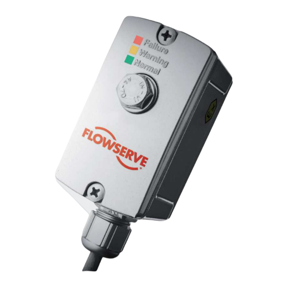
4.1 Wiring in the housing 1. Undo the cover screws in order to remove housing cover and gasket. Picture: Sensor IPS Detect 2. Strip the ends away from the protective covering of the supply cable as shown below. 50 mm... - Page 8 Page 8 of 35 IPS Detect 3. Insert the cable through the cable gland so that the ends easily reach the connection terminals. Picture: Cable ends 4. Connect the cable to the terminals. To open the terminal clamps use a screwdriver to press open and then insert the cable ends.
-
Page 9: Electrical Connection Check
Page 9 of 35 IPS Detect 5. Pull back the cable in order to remove any excess from within the terminal head. Subsequently tighten the cable gland. Picture: Connected cable Picture: Cable inside of the housing 6. Replace the gasket ensuring that it does not cover the LEDs and then tighten with the two screws. -
Page 10: Operation Ips Detect
Page 10 of 35 IPS Detect 5 Operation IPS Detect IPS Detect measures the vibration velocity of the pump in accordance with DIN/ISO 10816, 5199 and 9905 for preventive maintenance. Furthermore, an optional condition-monitoring element can be simply activated in order to monitor vibration up to 5.6kHz. - Page 11 Page 11 of 35 IPS Detect Picture: Configuration over FSK-Modem (HART -Modem) and EDD/DTM via FDT frame application Caution! Explosion hazardous area If FSK-Modem is to be installed in an explosion hazardous (Ex) rated area, then all associated national standards, directives, and safety instructions of the FSK-Modem...
-
Page 12: Configuration Vibration Velocity
Page 12 of 35 IPS Detect 5.1.1 Configuration vibration velocity Measurement of the vibration velocity (RMS) enables the condition of the pump to be determined. This gives an indication of the Mechanical wear within the pump unit. Examples for causes of high vibration velocity:... -
Page 13: Calibration Condition Monitoring
IPS Detect 5.2 Calibration condition monitoring Optionally, the IPS Detect can detect changes in the vibration Third-octave spectrum by comparing actual values with calibrated threshold values. Therefore, the sensor must be calibrated to the pump installation. Cavitation, misalignment, imbalance together with other wrong operation modes can subsequently be easily detected. -
Page 14: Calibration Condition Monitoring With Push Button
Page 14 of 35 IPS Detect 5.2.1 Calibration condition monitoring with push button 5.2.1.1 Starting calibration with the push-button 1. Start the pump and wait until normal operating conditions have been reached. 2. Loosen the screws and remove the housing-cover and gasket. Depress and hold the button down for approximately 3 seconds until red and yellow LED flash alternatively. - Page 15 Page 15 of 35 IPS Detect 6. To stop the calibration process, depress the push button for approximately 3 seconds until the green LED flashes. 7. At the end of calibration, the sensor changes to the condition-monitoring mode. The calibrated reference values are also saved even if the power supply is disconnected.
- Page 16 Page 16 of 35 IPS Detect 5.2.1.2 Deactivating the condition monitoring mode with the push-button 1. Loosen the screws and remove housing-cover and gasket. Depress the push- 2. Release the push-button until the green and yell 3. After approximately 1 minute the sensor will change to measuring mode and any existing calibration data is deleted.
-
Page 17: Calibration With Ips Vibrosoft Software
Page 17 of 35 IPS Detect 5.2.2 Calibration with IPS Vibrosoft software 5.2.2.1 Starting calibration with the IPS Vibrosoft software 1. Start the pump and wait until normal operation conditions are reached. 2. Start up the IPS Vibrosoft software and wait until is displayed. - Page 18 Page 18 of 35 IPS Detect 5.2.2.2 Deactivating the calibration condition monitoring using IPS Vibrosoft software 1. Click the button 2. Wait until the green display behind the button is then switched off. The sensor changes to measuring mode and exist calibration data is deleted. The condition monitoring is deactivated.
-
Page 19: Monitoring Operation
Page 19 of 35 IPS Detect 5.3 Monitoring operation You can simply check the pump operation by taking a quick glance at the pump and viewing the LED display. Online detection is possible with a 4-20mA interface directly connected to conventional control equipment. -
Page 20: Trouble-Shooting
Page 20 of 35 IPS Detect 6 Trouble-shooting Failure during operation and/or measurement modes are displayed as follows: Green, ye electronic failure / sensor failure The user needs to check that the power supply has been adequately connected before the system was started. -
Page 21: Maintenance And Repair
7.2 Repair The sensor IPS Detect has not been designed for repair. It is consistently not possible to replace the electrical/electronic parts. Importantly, it is forbidden to modify any part of the housing or electronics. -
Page 22: Technical Data
IECEx Ex ia IIC T4 Gb TUN 15.0038 If the sensor IPS Detect is to be installed in an explosion hazardous (Ex) area or other applications were approvals are necessary, then respective official documentation must be observed. As standard, the unit can... - Page 23 Page 23 of 35 IPS Detect Drawing IPS Detect Cable gland M16x1,5 Housing screw M8x60 Drawing IPS Detect with glue adapter OIM_FLS_IPS Detect_EN_14 Subject to technical changes! FLOWSERVE...
-
Page 24: Certification And Approvals
Page 24 of 35 IPS Detect 9 Certification and approvals 9.1 CE-mark, Declaration of conformity The device is designed in accordance with present safety requirements, and has been facility. The device complies with the applicable standards and regulations as cited in the EC declaration of conformity and thus complies with the statutory requirements of the EC Directives. - Page 25 Page 25 of 35 IPS Detect OIM_FLS_IPS Detect_EN_14 Subject to technical changes! FLOWSERVE...
- Page 26 Page 26 of 35 IPS Detect OIM_FLS_IPS Detect_EN_14 Subject to technical changes! FLOWSERVE...
-
Page 27: Eu Type Examination Certificate
Page 27 of 35 IPS Detect 9.2 EU Type Examination Certificate OIM_FLS_IPS Detect_EN_14 Subject to technical changes! FLOWSERVE... - Page 28 Page 28 of 35 IPS Detect OIM_FLS_IPS Detect_EN_14 Subject to technical changes! FLOWSERVE...
-
Page 29: Certification Of Conformity
Page 29 of 35 IPS Detect 9.3 Certification of Conformity OIM_FLS_IPS Detect_EN_14 Subject to technical changes! FLOWSERVE... - Page 30 Page 30 of 35 IPS Detect OIM_FLS_IPS Detect_EN_14 Subject to technical changes! FLOWSERVE...
- Page 31 Page 31 of 35 IPS Detect OIM_FLS_IPS Detect_EN_14 Subject to technical changes! FLOWSERVE...
- Page 32 Page 32 of 35 IPS Detect OIM_FLS_IPS Detect_EN_14 Subject to technical changes! FLOWSERVE...
-
Page 33: Accessories
Page 33 of 35 IPS Detect 10 Accessories 10.1 Cooling element max. surface temperature T without cooling element max. T = 80°C Order-No. 65010504 cooling element (1.) max. T = 120°C Order-No. 65010702 cooling element HT (2.) max. T = 160°C... -
Page 34: Software
IPS Vibrosoft software IPS Vibrosoft software has been developed purposely for professional analysis of the data, which has been generated by the IPS Detect sensor. Detailed evaluation of the data can subsequently be made in order to reveal very specific aspects of vibration. -
Page 35: Ips Datausb
IPS DataUSB Trend data memory is the ideal solution to store the vibration data, which were taken by the IPS Detect sensor, and serves as a uncomplicated communication interface for the vibration analysis. Independent from installation (stand alone or DCS integrated), condition data can be logged to a USB flash drive for a period of up to 3 years at permanent measurement.
Need help?
Do you have a question about the IPS Detect and is the answer not in the manual?
Questions and answers