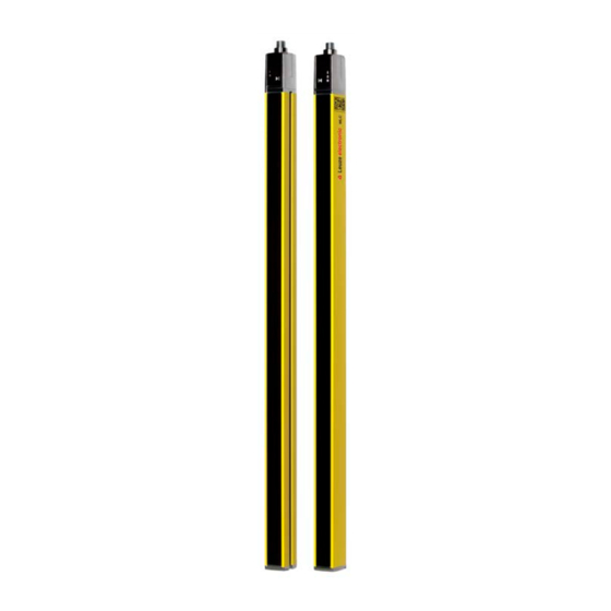
Leuze MLC 530 SPG Original Operating Instructions
Safety light curtains
Hide thumbs
Also See for MLC 530 SPG:
- Original operation instructions (89 pages) ,
- Translation of original operating instructions (94 pages)


Need help?
Do you have a question about the MLC 530 SPG and is the answer not in the manual?
Questions and answers